Jena NV200D
The Jena NV200D/NET controllers drive two piezo axes (X and Y) at 2-BM-B. They complement the existing Jena NV100D and are integrated with the FPGA trigger to step through a pre-loaded position list during tomography acquisitions.
EPICS IOC startup
Start the Jena NV200D EPICS support on arcturus:
[2bmb@arcturus]$ cd /net/s2dserv/xorApps/epics/synApps_6_3/ioc/JenaNV200D/iocBoot/iocJenaNV200D
[2bmb@arcturus]$ ../../bin/rhel9-x86_64/JenaNV200D st.cmd.Linux
The IOC can also be started and stopped from the iocs_start screen:
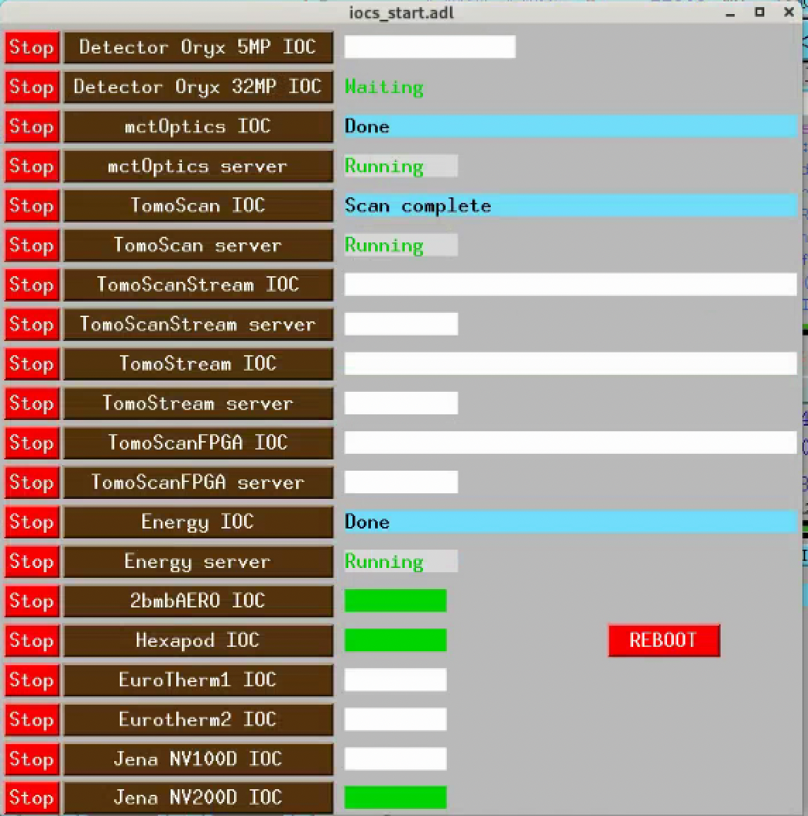
iocs_start control screen showing the Jena NV200D IOC entry.
Network configuration
Controller IP addresses:
X: 10.54.113.126
Y: 10.54.113.125
Note
Only one Telnet connection is allowed at a time. The EPICS IOC must be stopped before running the triggered-step Python script (see Triggered step mode), and restarted afterwards.
Device configuration
Both controllers must be set to Xon/Xoff (software) flow control via the Lantronix XPort web interface for the EPICS support to work correctly.
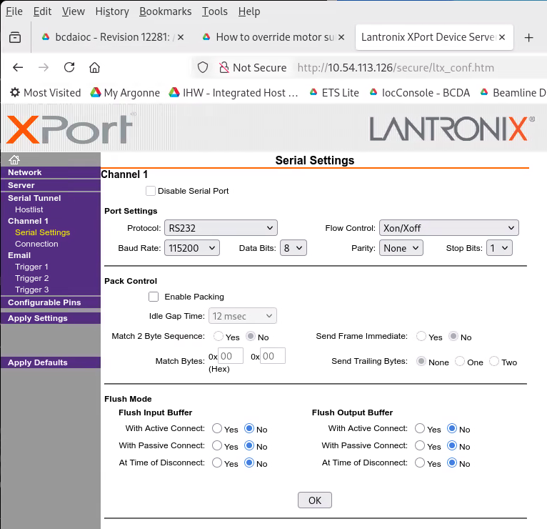
Lantronix XPort Serial Settings — Channel 1 flow control configuration (X axis).
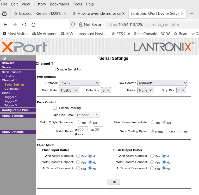
Lantronix XPort Serial Settings — Channel 1 flow control configuration (Y axis).
MEDM control screens
The Jena NV200D control is accessible from the lower-right corner of the mct_main screen under Jena NV200D Piezo:
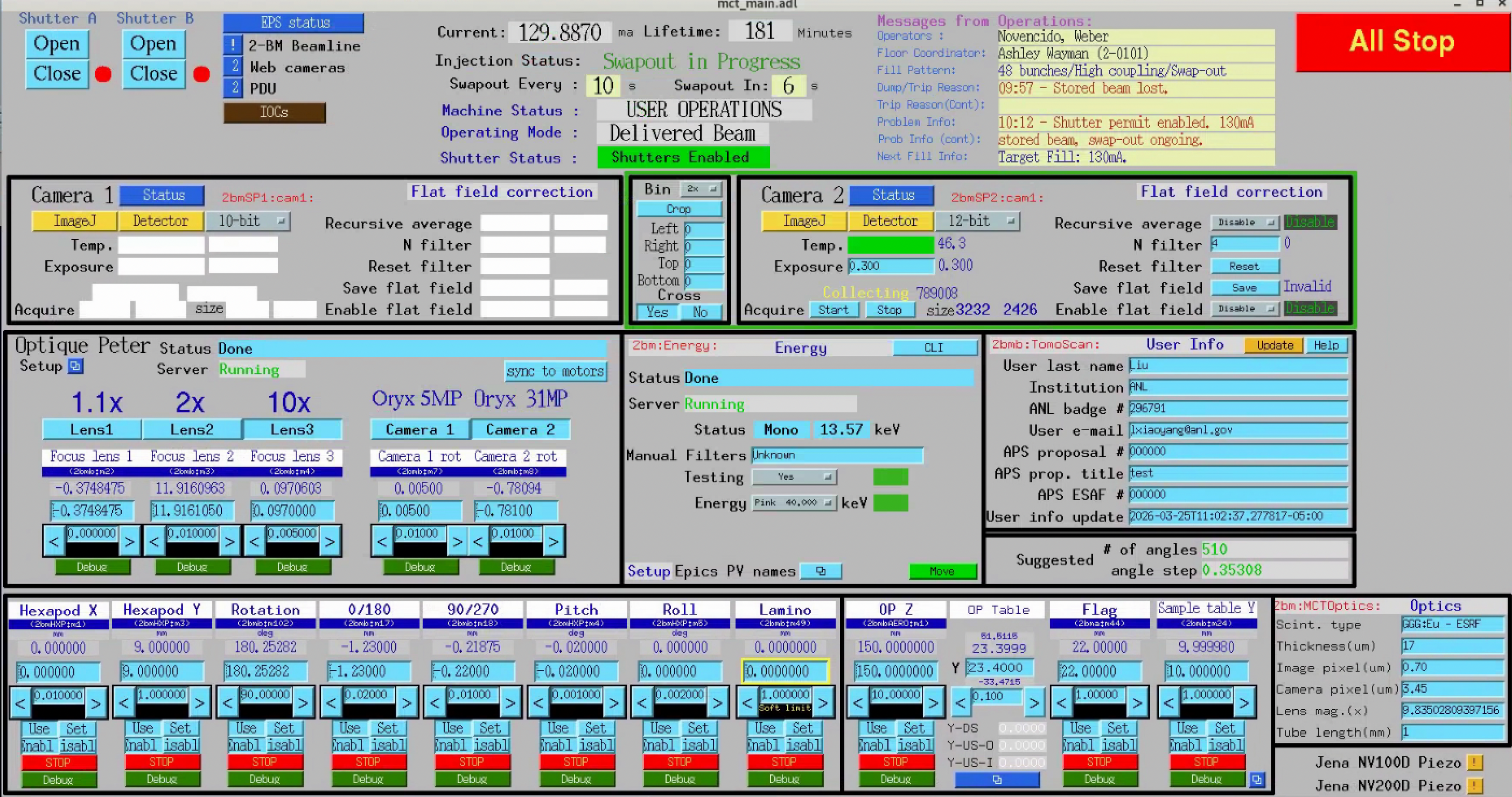
mct_main screen — Jena NV200D Piezo entry in the lower-right corner.
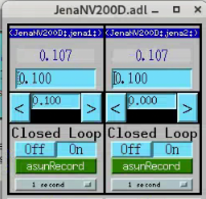
Jena NV200D MEDM screen showing both axes in closed-loop mode.
caqtdm interface
Start the caqtdm interface:
[2bmb@arcturus]$ /net/s2dserv/xorApps/epics/synApps_6_3/ioc/JenaNV200D/iocBoot/iocJenaNV200D/softioc/JenaNV200D.pl caqtdm
FPGA trigger integration
The FPGA sends a TTL pulse to the NV200D controllers to step to the next position during the camera readout interval. The JenaX and JenaY coaxial cables are connected to FPGA out2 and out3 respectively.
The delay before each pulse is set via two softGlue PVs (units: number of 10 MHz clock cycles, i.e. 100 ns per unit):
2bmbMZ1:SG:GateDly-2_DLY    # Y axis delay
2bmbMZ1:SG:GateDly-3_DLY    # X axis delay
Set the DLY field to the detector exposure time plus a safety margin:
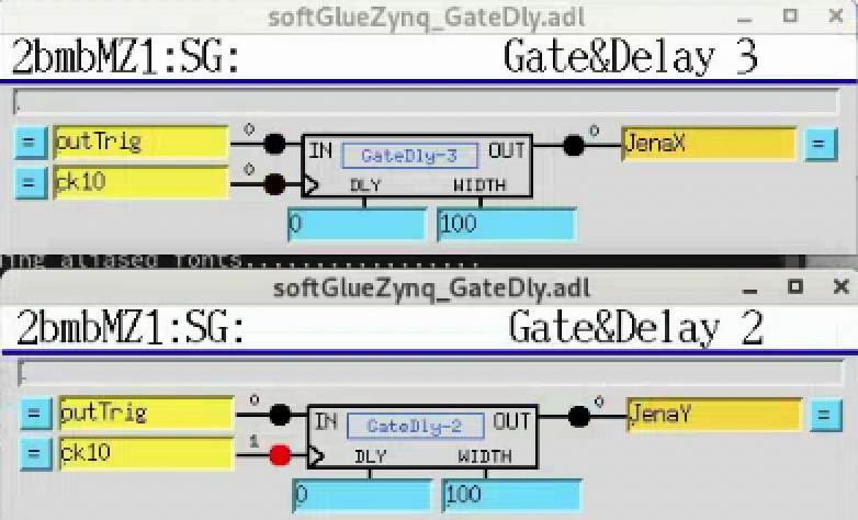
softGlueZync GateDelay screens for the two NV200D trigger channels.
Triggered step mode
Up to 1024 positions can be pre-loaded into each controller’s waveform buffer. Each rising TTL edge on the TRG IN connector (pin 3 of the I/O D-Sub, 0/3.3–5 V) advances the actuator to the next position.
Warning
Stop the EPICS IOC before running the script — only one Telnet connection is allowed at a time. Restart the IOC when done.
Install the required Python library:
pip install nv200 numpy
The script lives in the 2bm-procedures repository
(procedures/nv200_trigger_step.py).
Change to that directory before invoking it — the script writes
positions_x.txt / positions_y.txt to the current working
directory and looks for no input files. Run on a computer on the
beamline’s private subnet (e.g. arcturus):
[2bmb@arcturus]$ cd <path-to-2bm-procedures>/procedures
[2bmb@arcturus]$ python nv200_trigger_step.py [--n N] [--random]
(Replace <path-to-2bm-procedures> with wherever the
2bm-procedures
repository is checked out — e.g.
~/conda/2bm-procedures-decarlof.)
Arguments:
--n N— number of positions to load (default: 256, max: 1024)--random— use random positions instead of evenly spaced (linspace)
See the procedure page NV200D triggered-step buffer programming for the formal procedure definition (preconditions, parameters, steps, postconditions, failure modes) that this operational walk-through implements.
Example output:
Connecting to X (10.54.113.126)...
Connecting to Y (10.54.113.125)...
--- X axis ---
  Actuator stroke: 0.0 … 100.0 µm
  Auto-generated 256 evenly-spaced positions.
  Loading 256 positions into buffer...
    128/256
    256/256
  Running. 256 positions loaded. Current position: 0.000 µm
--- Y axis ---
  Actuator stroke: 0.0 … 100.0 µm
  Auto-generated 256 evenly-spaced positions.
  Loading 256 positions into buffer...
    128/256
    256/256
  Running. 256 positions loaded. Current position: 0.000 µm

Running. Each rising edge on TRG IN (I/O connector pin 3) steps to the next position.
Press Enter to stop...
Stopping...
Stopped. Manual control restored.
Note
Positions are stored in the controller’s RAM and are lost on power
cycle. Once operation is confirmed, they can be persisted to EEPROM
using the save_to_eeprom() method in the library.