Softglue
softGlueZynq is an EPICS-based FPGA I/O module developed at APS (Argonne) for flexible, user-configurable digital logic and timing.
In practical terms, it combines:
Hardware: a board based on a Xilinx Zynq SoC (FPGA + ARM processor) that provides digital I/O (and often counters, encoders, and timing signals) to interface with beamline or experimental equipment.
Firmware + EPICS IOC: the FPGA is preloaded with a “soft glue” fabric consisting of building blocks such as counters, dividers, gates, flip-flops, encoders, and delay generators. These blocks are exposed as EPICS PVs so you can “wire” them together in software (no FPGA HDL development required). The Zynq’s ARM core runs the EPICS IOC that talks both to the FPGA and the external control system.
softGlueZynq is typically used to implement programmable logic, timing, and signal conditioning between devices—for example, generating or conditioning triggers, combining signals for interlocks, or creating position-synchronized triggers from encoders—without designing custom FPGA firmware.
The Softglue IOC runs directly on the MicroZed module and starts automatically at boot.
Start MEDM or caQtDM
Start the MEDM interface:
[2bmb@arcturus ~]$ cd /net/s2dserv/xorApps/epics/synApps_SG/ioc/2bmbMZ1/
[2bmb@arcturus 2bmbMZ1]$ ./start_epics_2bmbMZ1
or start the caQtDM interface:
[2bmb@arcturus ~]$ cd /net/s2dserv/xorApps/epics/synApps_SG/ioc/2bmbMZ1/
[2bmb@arcturus 2bmbMZ1]$ ./start_caQtDM_2bmbMZ1 &
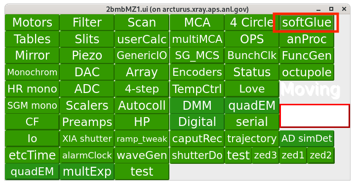
This opens the main Softglue control screen:
Softglue control
Accessing memPulseSeq
From the main Softglue panel, select:
softGlue → softGlueZynqMenu
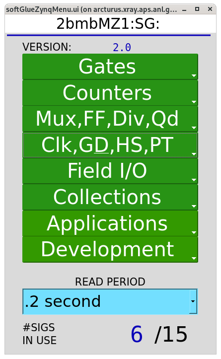
softGlueZynqMenu control
Then use:
Development → memPulseSeq
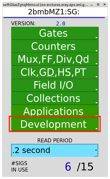
Development menu
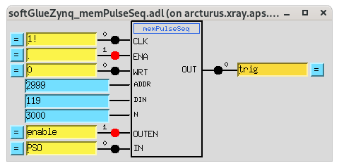
memPulseSeq component
Setting the pulse delay/width (GateDly)
You can adjust the timing (delay) and duration (width) of the output pulse using the GateDly block.
From the main Softglue panel, select:
softGlue → softGlueZynqMenu
to open the Clk, G&D, HS, PT page:
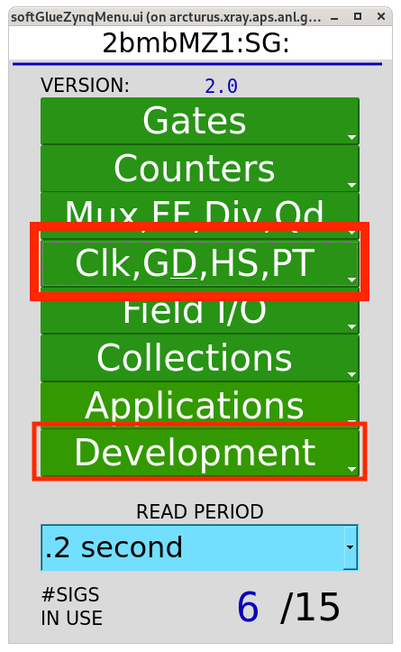
softGlueZynqMenu control
Select GateDly 1:
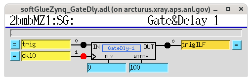
GateDly 1 selection
Set:
DLY = 0Width = 100
Notes:
DLYsets the delay from the incoming edge to the start of the output pulse.Widthsets how long the output pulse stays high.Widthis in units of 10 MHz clock cycles (100 ns per count). Therefore,Width = 100produces a \(100 × 100\,\mathrm{ns} = 10\,μ\mathrm{s}\) pulse.
Custom trigger pattern (trigILF)
The trigILF pulses are used as camera triggers. These pulses form a subset of the PSO pulse train and are selected using the Python function write_PSO_array.
Example:
(ops) [bmb@arcturus]$ python
Python 3.12.2 | packaged by conda-forge | (main, Feb 16 2024, 20:50:58) [GCC 12.3.0] on linux
>>> import macros_ILF as m
>>> m.write_PSO_array([0, 2, 4, 6])
>>>
In this example, PSO pulses 0, 2, 4, and 6 are used as camera triggers.
After loading the pulse array in Python:
Set
memPulseSeq.enable = 1to arm the component. When armed, the module triggers on the next incoming PSO pulses.Set
memPulseSeq.enable = 0to return the component to the idle (unarmed) state.
MUX selection (PSO vs trigILF)
To select between the raw PSO pulse train and the custom pattern generated
by write_PSO_array(), a 2:1 multiplexer (MUX2-1) is used.
input0= PSOinput1= trigILF
Changing the MUX select PV (MUX2-1_SEL_Signal) determines which signal
is routed to the camera trigger.
The MUX settings can be adjusted from the Collections / all softGlueZynq screen:
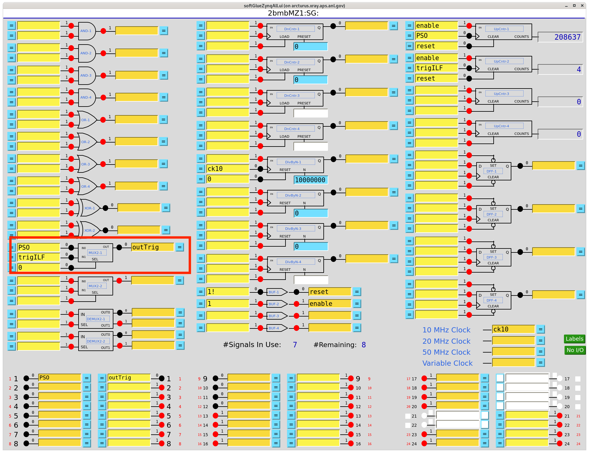
Softglue control – MUX settings
Route PSO pulses to the camera:
[2bmb@arcturus]$ caput 2bmbMZ1:SG:MUX2-1_SEL_Signal 0
Route trigILF pulses to the camera:
[2bmb@arcturus]$ caput 2bmbMZ1:SG:MUX2-1_SEL_Signal 1
Driving the two Jena piezo stages
During coded-aperture fly-scans, two additional GateDly blocks
(GateDly-2 and GateDly-3) generate the step pulses that
advance the two Piezosystem Jena NV200D/NET controllers (X and Y
axes of the nanoSXY 120 CAP XY flexure stage; see the
NV200D block of Beamline components for the hardware
description and the physical FPGA-out → axis wiring table).
Each block takes the camera trigger (outTrig) as input and
produces a delayed step pulse that lands during the readout
interval, after the exposure finishes:

GateDly-2 — takes outTrig as IN, ck10 (10 MHz) as
clock, DLY = 50000 (50000 × 100 ns = 5 ms delay), and
WIDTH = 100 (100 × 100 ns = 10 µs pulse width). Output is
the JenaX softGlue signal, routed through the field-I/O to
FPGA out2 and cabled to the X-axis NV200D TRG IN.

GateDly-3 — identical shape and settings; output is the
JenaY softGlue signal, routed through the field-I/O to FPGA
out3 and cabled to the Y-axis NV200D TRG IN. Same
5 ms delay, 10 µs pulse width.
The 5 ms delay is set to detector exposure time + a small safety
margin, so the piezo step happens after the sensor has
integrated the frame. Adjust DLY when the exposure time changes:
DLYandWIDTHare in 10 MHz clock cycles (100 ns per count).DLY = 50000→ 5 ms. Increase for longer exposures.WIDTH = 100→ 10 µs pulse (comfortably above the NV200DTRG INminimum sensitivity).
PVs (set from the caQtDM Gate&Delay page or with caput):
2bmbMZ1:SG:GateDly-2_DLYand2bmbMZ1:SG:GateDly-2_WIDTH2bmbMZ1:SG:GateDly-3_DLYand2bmbMZ1:SG:GateDly-3_WIDTH
Verifying the pulses are actually reaching the piezos
Two dedicated UpCntr blocks count the delivered step pulses so
an operator can confirm that both axes are stepping in lock-step
with the camera. Open the Collections → all softGlueZynq
(softGlueZynqAll.adl) screen:

softGlueZynqAll.adl during an active fly-scan. Right column,
top-to-bottom: UpCntr-1 (PSO master pulse count = 9,562,989),
UpCntr-2 (trigILF = 720, interlaced-trigger subset),
UpCntr-3 (X piezo pulse count = 5,819,549) and UpCntr-4
(Y piezo pulse count = 5,819,461). UpCntr-3 and UpCntr-4
should stay within one count of each other during any scan
(both are stepped by the same camera trigger); a drift between
them means one of the two piezo trigger paths is dropping
pulses.
The softGlue internal signal names JenaX and JenaY are set
to match the axis they drive: GateDly-2 → JenaX → FPGA
out2 → Jena X controller; GateDly-3 → JenaY → FPGA
out3 → Jena Y controller. Signal name, GateDly index, FPGA out
number, and axis are all consistent — no need to cross-check
against the wiring table for axis identification, though the
physical wiring in the NV200D block of Beamline components
is still the authoritative record for which cable runs where.