Beamline alignment
White beam
Center the source white beam on the fixed M3-24 front-end exit mask
(44.4 mm × 4.5 mm H × V optical aperture, OFHC copper, at
z = 24020 mm per APS_2191941 row 1; see
Beamline components). Earlier versions of this page cited
“50 mm × 3 mm” — that was an outdated pre-APS-U value; the post-
APS-U mask dimensions are above.
Start the detector in 2-BM-A:
(base) 2bmb@lyra ~ $ 2bmbOryx5MP medm
(base) 2bmb@lyra ~ $ 2bmbOryx5MP run
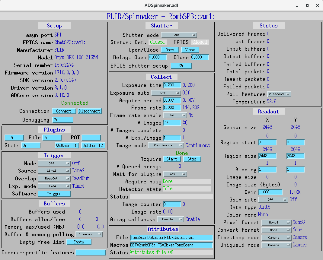
2-BM-A areadetector control screen
Start ImageJ:
(base) 2bmb@lyra ~ $ ImageJ
Configure the EPICS_NTNDA plug-in:

ImageJ EPICS_NTNDA plug-in
Lower M1 by setting:
Yaverage = -2 mmAngle = 0 mrad
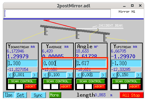
2-BM-A M1 mirror control screen
Lower the DMM by setting the three vertical stages (USY-OB, USY-IB, and DSY)
to -19 mm.
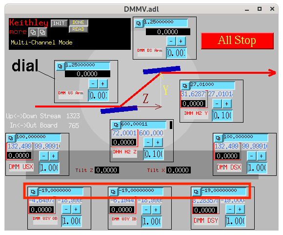
DMM control screen
Adjust the camera vertical position (2bma:m21) until the white beam
is visible:
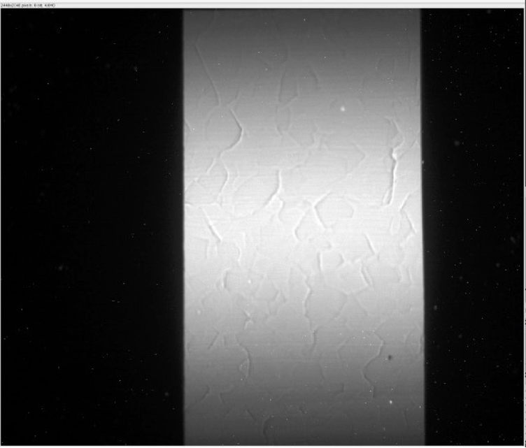
White beam at 2-BM-A with 1 mm Al filter Exposure 0.004 s, 20 mm glass filter
Remove the 1 mm Al filter.
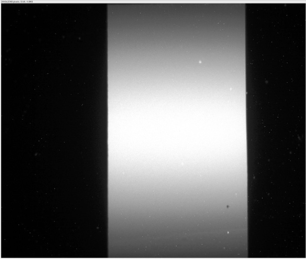
White beam at 2-BM-A without any filter Exposure 0.004 s, 20 mm glass filter
Plot a vertical line profile of the white beam intensity:
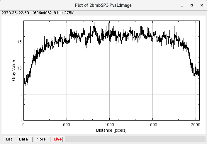
White beam vertical intensity plot
If the profile is not symmetric, request beam steering from the control room in 10 µrad steps:
Insert the mirror by setting:
Yaverage = 0 mmAngle = 0 mrad
Recalibrate the mirror:
Adjust
Yaverageuntil the mirror cuts the white beam image in half.Adjust the mirror angle until the reflected beam disappears.
After completing steps 1 and 2, reset the mirror Yaverage and angle to
zero.
Warning
To enhance the visibility of the reflected beam, enable the Proc1 plugin. In the Flat Field Normalization section, click Save Flat Field and Enable Flat Field.
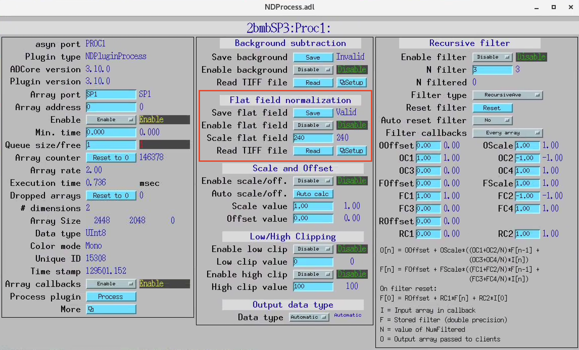
Pink beam
Set the mirror angle to 2.618 mrad (0.15°). Move the camera up until
the pink beam is visible.
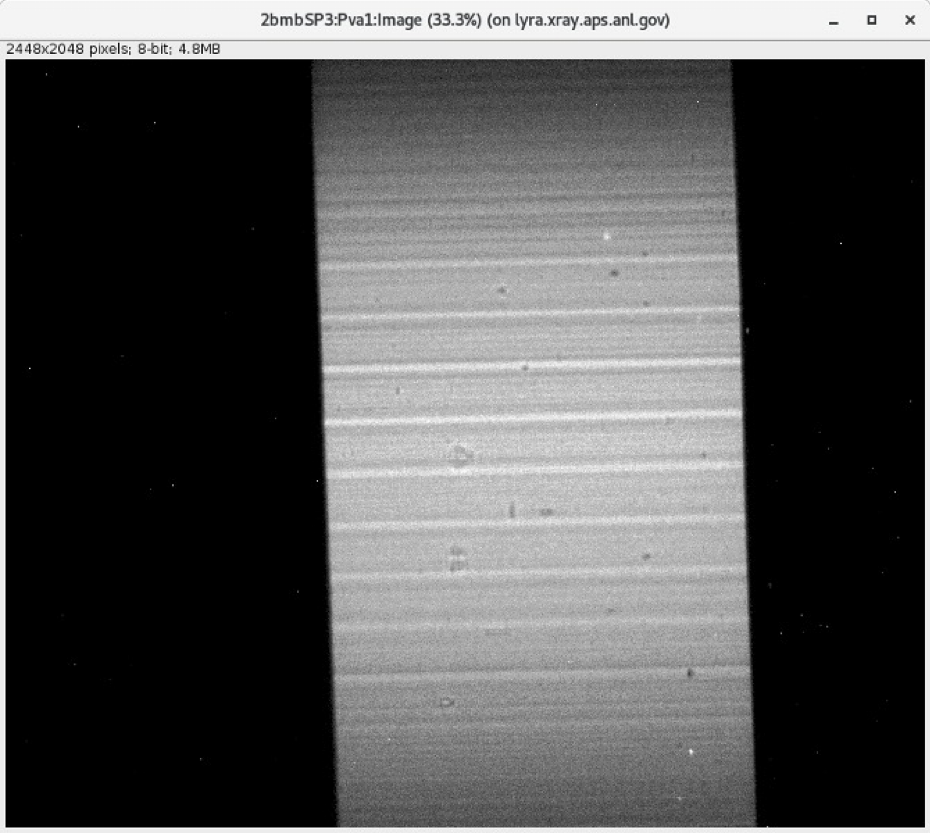
Pink beam after steering Exposure 0.004 s, 20 mm glass filter
Adjust the camera vertical position until the pink beam image is centered,
then set the camera Y position to 0.
Mono beam
Set the DMM vertical stages to:
USY-OB = 0 mm
USY-IB = 0 mm
DSY    = 0 mm
Set the DMM Upstream arm angle to 0°.
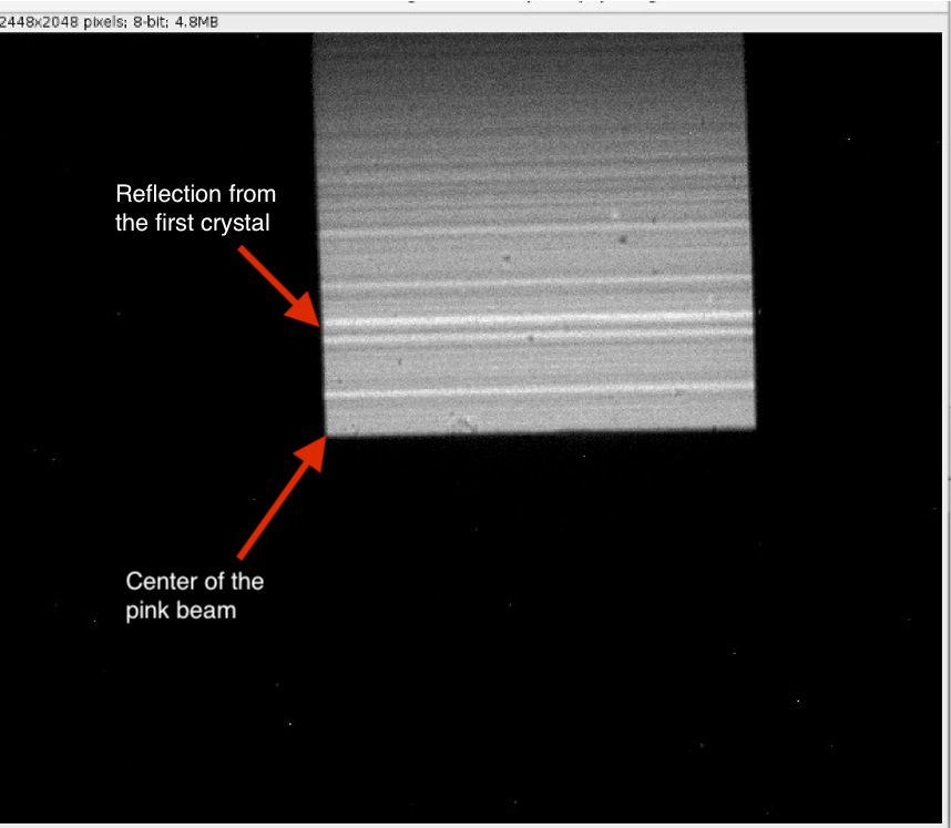
Pink beam cut in half by the first DMM crystal
Recalibrate the DMM table height and the first crystal angle:
Adjust USY-OB, USY-IB, and DSY until the first crystal cuts the pink beam image in half.
Adjust the first crystal angle (DMM Upstream arm) until the reflected beam disappears.
After completing steps 1 and 2, reset USY-OB, USY-IB, DSY, and the DMM Upstream arm angle to zero.
Recalibrate the second crystal angle:
Move the DMM vertical stages (USY-OB, USY-IB, and DSY) down by 10 mm.
Move DMM M2Y down until the second crystal cuts the pink beam in half.
Adjust the second crystal angle until the reflected beam disappears.
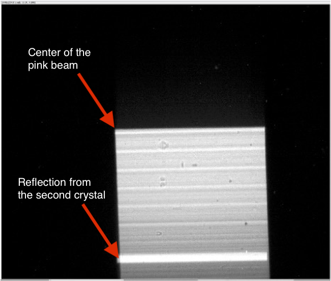
Pink beam cut in half by the second DMM crystal
After completing steps 1–3, set:
DMM M2Y = 10 mmDMM Downstream arm angle = 0°
Locate the DMM monochromatic beam:
Move the DMM into the beam (set USY-OB, USY-IB, and DSY to 0).
Set the DMM Upstream arm to
1.25°.
The distance between the first and second crystal centers is approximately 600 mm, so:
\(\tan(2 \times 1.25^{\circ}) \times 600 \approx 26.196 \text{ mm}\)
Set
DMM M2Y = 26.196 mm.Set detector Y (
2bma:m21) to26.196 mm.
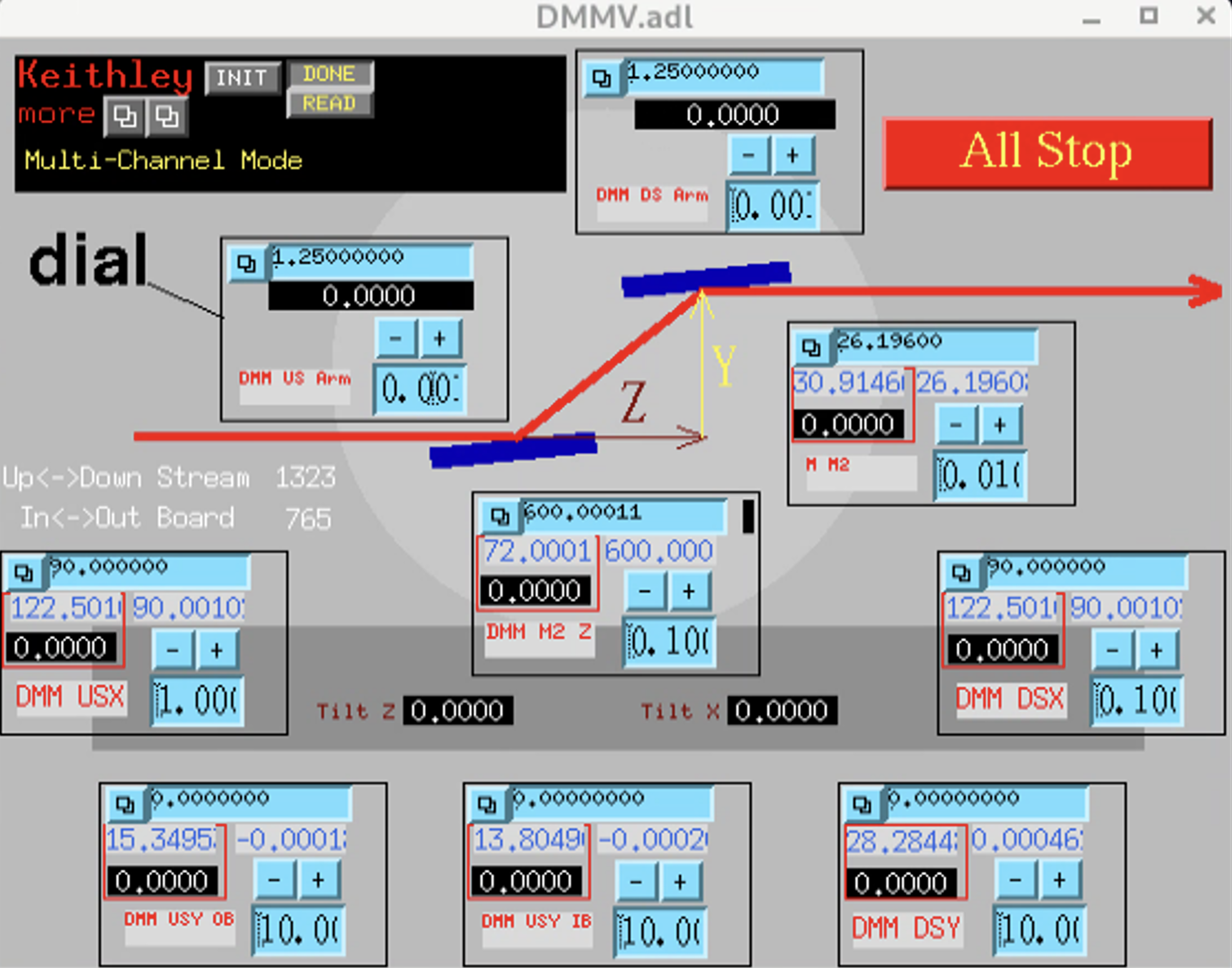
DMM in position
Adjust detector Y (2bma:m21) until the DMM monochromatic beam is
visible:
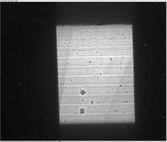
DMM monochromatic beam
Maximize the intensity and beam size by adjusting only:
DMM Downstream arm
DMM M2Y
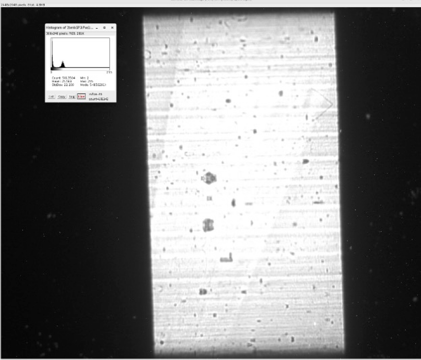
Optimized DMM monochromatic beam
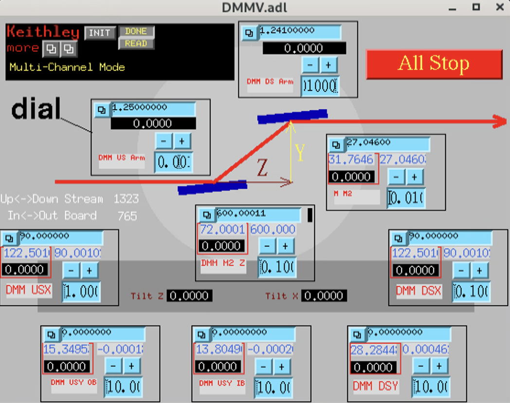
DMM position after monochromatic beam optimization
Set the second crystal angle (DMM Downstream arm) to 1.25°.
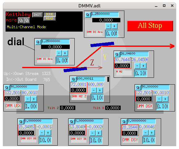
DMM position after monochromatic beam optimization and second crystal reset
If the optimized DMM M2Y is 26.046 mm instead of the calculated 26.196 mm, the effective distance between the first and second crystal centers is 596.56 mm.
For the full procedure to calibrate the DMM energy using a channel-cut crystal and multilayer tables, see Energy calibration.