Beamline components
Reference inventory of the physical hardware that makes up 2-BM, walked from the source to the detector. Each component is listed once, with the fields needed to drive it (Family / role / intrinsic specs) and the fields needed to reason about how it moves relative to everything else (what it is mounted on, what rides on top of it).
This page is the source of truth for the beamline as an assembly. Per- component operating instructions live in Beamline control (beamline control) and the Operation section. Structured, cora-consumable recipes that use this hardware live in Procedures.
Note
“Mounted on” captures the kinematic chain, distinct from compositional ownership. A stage mounted on the rotary co-rotates with it; the same stage mounted under the rotary translates the rotation axis in lab coordinates. Alignment, error propagation, and limit-handling all depend on which is which.
Overview
02-BM XSD beamline layout (APS drawing A342-RT1000, Rev 02, 05/27/26). Top: building footprint with the 2-BM-A and 2-BM-B hutches. Bottom: beamline elevation with components labelled in walking order through 2-BM-A; the 2-BM-B hutch (~49–57 m from the source) contains a second set of L3 slits at z ≈ 50500 mm. Source PDF: A342-RT1000-02.pdf.
Physical walk, source to detector (z values from the APS reference table, in millimetres from the centre of the storage-ring straight section; the beamline runs from z = 24020 at the FE exit mask to z = 56764 at the photon stop):
Storage ring source
  -> A-shutter (front-end)          (in 2-BM-A; z TBD)
  -> L3 Slits + Filters             (z = 25225 mm)
  -> Y3-30 Mirror                   (z = 27626 mm)
  -> Double Multilayer Mono (DMM)   (z = 29335 / 29934 mm)
  -> Flag (diagnostic phosphor)     (z = 32500 mm)
  -> B-shutter (P6-50 Safety)       (z = 33343 mm)
  -> B-station Slits (L3-style)     (z = 50500 mm; in 2-BM-B)
  -> Sample stack                   (in 2-BM-B; optical table + tower)
  -> Detector system                (MCTOptics + Optique Peter Z + detector table)
Passive components (FE exit mask, K4-21 collimator, Be windows, white-beam stop, baffles, beam transports, photon stop) sit between these elements at the z positions listed in the inventory table below.
Each block below expands into individual components with their intrinsic properties and kinematic relations.
Personnel and access interlocks
The Personnel Safety System (PSS) and the APS-wide Access Control
and Interlock System (ACIS) gate beam admission to 2-BM. Neither
exposes a commandable Asset — both publish read-only status PVs
that downstream procedures and shutter-open commands check before
acting. They are not beam-conditioning devices and do not appear in
the z-ordered “Physical walk” above; they live here, alongside the
overview, because every beam-path component below is conditional on
both reading ON.
PSS hutch search status
The Personnel Safety System publishes a per-hutch “secure” enum
that reads ON when the hutch is searched and locked (and the
PSS is willing to admit beam) and OFF when the search is broken
(door open, search active, manual override, etc.).
- Family:
PSS interlock readback (read-only; not a Family in the cora 2-BM inventory — these are operational status PVs, not commandable Assets).
- Hosted on:
s2pvgate.xray.aps.anl.gov:5064(PSS gateway; same host as the shutterBeamBlockingMPVs).
PV |
Description (DESC) |
Meaning |
|---|---|---|
|
|
2-BM-A hutch |
|
|
2-BM-B hutch |
Both PVs share the same enum:
STATE 0 =
OFF→ hutch not secure (search active or broken; PSS will not admit beam).STATE 1 =
ON→ hutch secure (searched and locked; PSS permits beam).
These are the predicates the Enable beamline for beam
(enable_beamline) stub procedure uses for its
beamline_enabled postcondition. Both must read ON before
the FES open command (S02BM-PSS:FES:OpenEPICSC) will be
honoured.
ACIS upstream permit
The APS Access Control and Interlock System exposes a single
“upstream permit” PV that aggregates storage-ring health,
injection state, APS-wide permits, the per-beamline PSS state,
and the BLEPS fault chain into one boolean. If it reads ON,
all of the upstream conditions required to admit beam to 2-BM
are met – the FES open command will be honoured.
- Family:
ACIS upstream permit (read-only; analogous to the PSS
SecureMPVs above but at a higher level of aggregation).- Hosted on:
s2pvgate.xray.aps.anl.gov:5064.
PV |
Description ( |
Meaning |
|---|---|---|
|
|
FES open permitted |
Enum:
STATE 0 =
OFF→ ACIS does not permit the FES to open (some upstream condition failed – could be storage ring down, BLEPS fault latched, PSS not searched, etc.).STATE 1 =
ON→ ACIS permits the FES to open. The individual upstream conditions are all green.
This is the single PV the Enable beamline for beam
(enable_beamline) stub procedure uses to test the composite
“upstream OK” condition. It replaces the earlier
“BLEPS-clear AND machine-state-OK” pair of TBDs because ACIS
already composes both.
Beam delivery
The formal inventory of front-end and transport components, with positions, apertures, materials, tolerances, and reference drawing numbers, is maintained as the 02-BM Beamline Component Reference Table (APS_2191941, PDRC TN25-015, approved 04Aug2025, edited 25Sept2025 following Commissioning with MLs and DMM motor-controller RSS removal). This is the post-APS-U revision and supersedes the earlier APS_1404611 (2013 pre-APS-U baseline).
That document is the source of truth for positions and shielding; the summary below reproduces it in walking order (source to hutch) and expands the components that are operationally addressed at run time (slits, mirror, monochromator, safety shutter) into per-component blocks for cora.
Note
Several z positions in the per-component blocks further down this page (Y3-30 Mirror, DMM crystals, P6-50 assembly) still carry the pre-APS-U values from APS_1404611 and need a per-block reconciliation pass against APS_2191941. The Be window stack (see “Be window stack” below) and the P6-50 reference-drawing numbers are already updated from APS_2191941.
Coordinate convention (from the APS_1404611 reference table linked above):
X= horizontal, positive outboard [mm]Y= vertical, positive up [mm]Z= along beam from the centre of the straight section [mm]X/Ypositions are relative to the nominal white-beam centrelineMasks and collimators are referenced to the aperture centre
♥ standard bending-magnet centreline (1.35 mrad inboard)
♠ alternate centreline (5.1 mrad up at Y3-30 mirror)
♦ alternate centreline (5.23 mrad up at Y3-30 mirror)
The Z reference point varies per component class (a superscript on
the Z value in the original APS table; reproduced as the ref
column in the inventory below):
1 — upstream face of thermal component (FE exit mask, Be windows, white-beam stop, W collimator, safety shutter, SS baffle)
2 — centre of optic (slits, mirror, DMM crystals)
3 — upstream face of shielding material (K4-21 collimator, beam transports, photon stop)
Beam-conditioning inventory (source to hutch)
The table below lists only the components that condition the beam (shape and energy). Passive hardware — FE exit mask, K4-21 collimator, Be windows, white-beam stop, W collimator, SS baffle, shielded beam transports, photon stop — is not reproduced here; the linked APS reference table at the top of this section is the authoritative full inventory. Item numbers below match the APS table for cross- reference.
# |
Component |
z [mm] |
ref |
Notes |
|---|---|---|---|---|
2 |
L3 Slits with Filters |
25225 |
2 |
Operational; see block below. Splits into L3 Slits (shape) and L3 Filters (energy absorption); shared assembly. |
4 |
Y3-30 Mirror |
27626 |
2 |
Silicon · defines the ♠ / ♦ alternate centrelines · operational, see block below |
5 |
Double Multilayer Monochromator |
29335 / 29934 |
2 |
Silicon · two crystals (Y offsets 9.0 / 41.0 mm) · operational, see block below |
— |
B-station Slits |
50500 |
2 |
Second four-blade L3-style slits in 2-BM-B (no filter changer paired). Not in APS_1404611; z read from layout drawing A342-RT1000-02. Operational, see block below. |
Common position tolerances across all rows: dx = dy = 250 µm, dz = 5 mm.
All four items are operational (have command surfaces) and are expanded in operational components. The P6-50 safety shutter (row 10 in APS_2191941) is also operational but gates the beam rather than conditioning it; it appears as its own block at the end of the operational-components section.
Front-end exit mask (M3-24)
First beam-defining aperture on the 2-BM beamline; passive, water-cooled, fixed in place. Defines the white-beam optical aperture that downstream optics see. From APS_2191941 row 1:
- RSS tag:
02-BM-A-F-01- Reference drawing:
4102020101-240000- z position:
24020 mm (= 24.020 m from the centre of the storage-ring straight section; ref convention 1 = upstream face of the OFHC copper block)
- Optical aperture (H × V):
44.4 mm × 4.5 mm
- Material:
OFHC copper
- Position tolerance:
dx = dy = 250 µm, dz = 5 mm
- PSS [EPS] water flow rates:
1.5 LPM nominal, 1.0 LPM minimum
- Source-current limit:
220 mA
- Notes:
Aperture centred on the standard bending-magnet centreline (1.35 mrad inboard); the upstream optics table is rotated to accommodate the storage-ring wall. Thermal analysis is in APSU_2286907.
Note
No cora Asset for the FE exit mask itself — it has no command
surface (passive, fixed aperture, no actuator). Cora’s Mask
descriptor stub (the placeholder cora opened for this question)
is the appropriate model: a registered inventory item with
physical / shielding parameters but no commandable axes.
Answers cora ALIGN-2.
Earlier 2bm-docs versions of Beamline alignment cited the mask as “50 mm × 3 mm (H × V)” — that was an outdated pre-APS-U value; the post-APS-U dimensions above are authoritative.
Be window stack
Three Be windows along the beam path, all OFHC-housed; total Be thickness 0.63 mm. From APS_2191941 (post-APS-U), rows 5 / 8 / 9:
# |
Component |
Reference drawing |
z [mm] |
Be thickness |
Aperture H x V [mm] and offset |
|---|---|---|---|---|---|
5 |
W4-20 Be Window |
|
28718 |
0.25 mm |
120 x 15; on-centreline (x=0, y=0) |
8 |
W4-60 Be Window |
|
30804 |
0.13 mm |
25 x 120; x = -7.4 mm (inboard), y = +22.3 mm (up) |
9 |
Be Window (no separate label) |
|
32417 |
0.25 mm |
8.8 x 145; on-centreline (x=0), y = +31.0 mm (up) |
Position tolerances per row: dx = dy = 250 µm, dz = 5 mm. PSS [EPS] water flow rates: 1.5 LPM nominal, 1.0 LPM minimum (each window). Ref. z is the upstream face of the OFHC housing (ref convention 1 for W4-60 and the unlabelled Be window; ref convention 3 (upstream face of shielding material) for W4-20).
Note
No standalone cora Asset for the Be windows; they are passive beam-path elements with no command surface. Recorded here as per-Run provenance / shielding inventory data. Answers cora BEAM-2.
Operational components
The L3 slits and filters share an ops page; the mirror and DMM each have their own. Pre-APS-U pages are noted as such — those entries are candidates for reconciliation against the post-APS-U layout.
2-BM has two shutters: an A-shutter at the front end (first
gating element on the beamline, in 2-BM-A) and the P6-50 safety
shutter (B_shutter) further downstream. Both are listed below.
A-shutter (front-end)
- Role:
First beam-gating element on the beamline; located in 2-BM-A upstream of the slits
- Family:
Shutter (would be a second instance of the cora
ShutterFamily. The cora 2-BM assets inventory atdocs/deployments/2-bm/assets.mdcurrently lists only oneShutterAsset,StationShutter, which is the B-station P6-50 safety shutter below; the A-shutter is not yet registered and needs a distinct Asset name (cora has not chosen one — a role-name likeFrontEndShutterwould follow the same convention asStationShutter, naming the shutter by what it gates rather than by vendor or PV).)- Mounted on:
Front-end stand (floor-referenced)
- Carries:
(beam gating only)
- z position:
TBD (upstream of the L3 Slits; not separately listed in the APS reference table)
- EPICS prefix:
S02BM-PSS:FES- Open command:
S02BM-PSS:FES:OpenEPICSC- Close command:
S02BM-PSS:FES:CloseEPICSC- Status readback:
S02BM-PSS:FES:BeamBlockingM(DBF_ENUM, read-only; hosted on the PSS gateways2pvgate).STATE 0 =
OFF→ beam is not being blocked → shutter OPEN.STATE 1 =
ON→ beam is being blocked → shutter CLOSED.
Note the inverted semantics: the PV reports the blocking state, not the shutter position. After issuing
OpenEPICSC/CloseEPICSCconfirm the state by readingBeamBlockingM(cagetreturns the stringOFF/ONwhen called with-S; the integer 0 / 1 by default).- Notes:
Independent of the P6-50 personnel-safety shutter (
B_shutter, below) further downstream. Both must be open for beam to reach 2-BM-B. Operational practice: the A-shutter is opened at the start of an experimental session and kept open continuously to preserve the thermal stability of the beamline optics (mirror, monochromator). Per-scan beam gating is done on the downstream P6-50 (B_shutter) instead; see the P6-50 block below for the TomoScan integration.
Note
2-BM-A motor controller. Every 2bma:mNN motor cited in
the 2-BM-A blocks below (L3 Slits, Y3-30 Mirror, DMM, B-station
Slits, etc.) is a slot on the OMS-VME58 card in the ioc2bma
crate — cora Asset FrontEndDrive. None of those
driven stages are themselves modelled as cora Assets yet (the
front-end / beam-conditioning band stays in cora’s Pending
list); the controller Asset ships in isolation as the
addressability handle for “controller-level” Procedures.
L3 Slits
- Role:
Beam-shape conditioning, upstream of the mirror
- Family:
Slit (listed as “Pending in code” in the cora Equipment BC families catalog at
docs/catalog/families.md; not yet a registered Family. Standard APS L3-20 four-blade slits — two horizontal (X−, X+) and two vertical (Y−, Y+) blade motors, plus per- direction derivedSize/Centercalc axes.)- cora Asset:
ConditioningSlit(proposed name; not yet registered. Used as thetarget_asset_idsvalue bycalibrate_slit_blade_throw(Calibrate the throw of each L3 slit blade motor) and bycentre_and_close_slits(Centre and close an L3-style slit aperture).)- Mounted on:
Front-end stand (floor-referenced)
- Driven by:
FrontEndDrive(coraMotionControllerAsset already registered incora/docs/deployments/2-bm/assets.md; pending controller_id back-reference from this Asset once it registers)- Carries:
(beam conditioning only)
- z position:
25225 mm (ref 2: centre of optic; shared with Filters)
- Position tolerance:
250 µm (x, y), 5 mm (z)
- Reference drawing:
L3200000-03.pdf
- As-built drawings:
- MEDM screen:
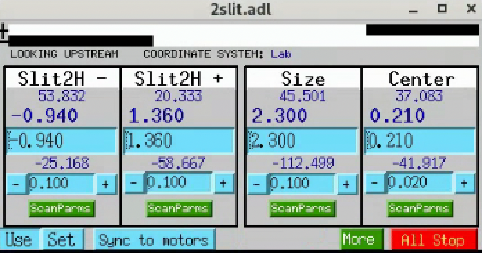
2slit.adl(running onarcturus)- EPICS prefix:
2bma:(horizontal motorsm14for A Slit X− [inboard],m13for A Slit X+ [outboard]; vertical motorsm15for A Slit Y+ [up],m16for A Slit Y− [down])- Virtual motor PVs:
the four composite Size/Centre
ao-record PVs below drive both blades of a pair together. Hosted onioc2bmb1.xray.aps.anl.gov:5064(the same IOC that hosts the B-station slit calc records, despite the2bma:prefix on both). These are the PVs the2slit.adlMEDM screen wires to theSizeandCentertext-entry boxes; the values you set on the screen propagate through downstream calc records to the individual blade motors.PV
Limits (mm)
2bma:Slit1Hsize+93.95 / -24.05
2bma:Slit1Hcenter+34.73 / -24.27
2bma:Slit1Vsize+71.29 / -66.71
2bma:Slit1Vcenter+23.47 / -45.53
The slits at 2-BM are standard APS L3-20. Technical as-built drawings are available here.
Note
“Inboard” follows the APS X convention: positive X is outboard
(away from the ring centre), negative X is inboard (toward the
ring centre). The screen below is oriented LOOKING UPSTREAM,
so on-screen left corresponds to inboard.
2slit.adl — horizontal-slits control screen (“LOOKING
UPSTREAM”, Lab coordinate system). The two leftmost columns
drive the individual blade motors: 2bma:m14 for the X− blade
(inboard) and 2bma:m13 for the X+ blade (outboard). The
Size and Center columns are calc-driven composites that
move both blades together to set the aperture width and centre.
2slit.adl — vertical-slits control screen (same orientation
and layout as the horizontal screen). The two leftmost columns
drive the individual blade motors: 2bma:m15 for the Y+ blade
(up) and 2bma:m16 for the Y− blade (down). The Size and
Center columns are calc-driven composites that move both
blades together to set the aperture height and centre.
Note
cora Asset registration intent. When the Slit Family
graduates from Pending, register this assembly as Asset
ConditioningSlit with the following structure (mirrors the
Hexapod / Rotary patterns
already in cora/docs/deployments/2-bm/assets.md):
Family:
SlitMounted on: front-end stand (floor reference)
controller_id back-reference:
FrontEndDriveSettings (blade motors):
2bma:m13(H+ outboard),2bma:m14(H− inboard),2bma:m15(V+ up),2bma:m16(V− down)Settings (virtual / calc-driven aperture):
2bma:Slit1Hsize,2bma:Slit1Hcenter,2bma:Slit1Vsize,2bma:Slit1Vcenterz position: 25225 mm (from APS reference table)
Per-blade calibration field
calibration_slope_pix_per_mm(one per blade motor), seed values + conditions from the Calibrate the throw of each L3 slit blade motor field-test table for the “A station — after MRES fix” run (2026-06-14).Target of Procedure
calibrate_slit_blade_throw(Calibrate the throw of each L3 slit blade motor) and Procedurecentre_and_close_slits(Centre and close an L3-style slit aperture).
L3 Filters
- Role:
Energy filtering (selective absorption upstream of the mirror)
- Family:
Filter (cora
FilterFamily; the device is preregistered in the 2-BM Pending list atdocs/deployments/2-bm/assets.mdas AssetFilterwith FamilyFilter.Filteris the thing-noun the device IS (anatomy); the paddle-changing mechanism is operational behaviour, captured as affordances on the Family rather than baked into the Family name — cora’s noun-LAST rule rejects the agent-noun reading ofFilterChanger. Two independent paddle sets — upstream and downstream — with up to four filter materials per side, plus a None / LowLimit reference per side.)- Mounted on:
Front-end stand (shared assembly with L3 Slits)
- Carries:
(beam conditioning only)
- z position:
25225 mm (ref 2: centre of optic; shared with Slits)
- Position tolerance:
250 µm (x, y), 5 mm (z)
- Reference drawing:
L3200000-03.pdf
- IOC:
2filter(running onarcturus)- MEDM screens:
2filter.adl(user),2filter_setup.adl(admin)- EPICS prefix:
2bma:(filter macrofltr1:; motorsm17upstream,m18downstream; lock calcuserCalc10)
Current configuration. The L3 filter changer has two independent
paddle sets, mounted upstream and downstream of the slits assembly.
Each side carries up to four filter materials, plus a None (empty)
position and a LowLimit hardware reference.
2filter.adl is the operator screen used to drive the filters
during a run; 2filter_setup.adl is the admin screen used to
program the paddle labels and the motor-drive positions each label
maps to. Both screens are part of the 2filter IOC.
2filter.adl — operator-facing filter selector. Each button
moves the corresponding motor to the position bound for that
material (see admin screen below). None pulls the paddle
clear; LowLimit returns to the hardware reference.
Materials currently bound (read from the screen above):
Upstream paddles: 1 mm C, 150 µm Al, 600 µm Al, 1 mm Al
Downstream paddles: 600 µm Al, 150 µm Al, 300 µm C, 50 µm C
Warning
Downstream paddle (`2bma:m18`) motor is failed. Operator-
reported 2026-06-19. The motor is currently parked at position
107.19 mm, ~1 mm beyond the None bind at 106.000 mm — i.e.,
paddles are clear of the beam, but the motor cannot be commanded.
Bindings (see table below) remain valid in the IOC and will
return to use when the motor is repaired or replaced. Repair
is not expected in the near term; the planning assumption for
the foreseeable future is that filter selection at 2-BM is via
the upstream paddle (m17) only.
The upstream paddle (`2bma:m17`) is fully operational —
paddles 1 mm C, 150 µm Al, 600 µm Al, 1 mm Al,
and None are all selectable. Earlier revisions of this page
said upstream “hardware not in service”; that was incorrect and
has been removed. Filter selection at 2-BM today is therefore
available via the upstream paddle only, until m18 is repaired.
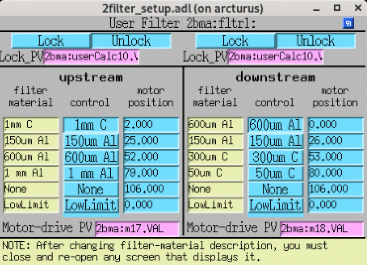
2filter_setup.adl — administrative screen for the L3 filter
changer. Used to (a) edit the material description on each paddle
and (b) set the motor-drive position each material maps to, per
side. The four-paddles-per-side limit and the upstream /
downstream split are set here. When a material description is
changed, any open 2filter.adl instance must be closed and
re-opened to pick up the new label.
Motor-drive PVs: upstream 2bma:m17.VAL,
downstream 2bma:m18.VAL.
Position bindings (read from ``2filter_setup.adl``):
Upstream material |
|
Downstream material |
|
|---|---|---|---|
1 mm C |
2.000 |
600 µm Al |
0.000 |
150 µm Al |
25.000 |
150 µm Al |
26.000 |
600 µm Al |
52.000 |
300 µm C |
53.000 |
1 mm Al |
79.000 |
50 µm C |
80.000 |
None |
106.000 |
None |
106.000 |
LowLimit |
0.000 |
LowLimit |
0.000 |
Position units are millimetres, per caget 2bma:m18.EGU
(operator-verified 2026-06-19; PV returns mm). The regular
~25-26 mm spacing across the 0–106 mm range is the physical paddle
pitch.
Y3-30 Mirror
- Role:
Vertical-deflecting mirror; defines the alternate beam centrelines
- Family:
Mirror (Pending in cora: Asset
Mirrorappears in the Pending table atdocs/deployments/2-bm/assets.md(role-name convention set by cora’s #111, after earlier candidate namesMirror_2BMandY3-30_mirror); FamilyMirroris listed as “Pending in code” atdocs/catalog/families.md. Composes a mirror body with an in-vacuum stripe selector and an external optical-table sub-assembly carrying Y / X / Z stages.)- Mounted on:
Optical table (six physical motors
2bma:m1–2bma:m6; the per-end Y motors are driven via2postMirror.dband the table X motors via the energy-change IOC; see the Mirror optical table block below)- Carries:
(beam conditioning only)
- z position:
27626 mm (ref 2: centre of optic; mirror-1 axis)
- Position tolerance:
250 µm (x, y), 5 mm (z)
- Material:
Silicon
- Mirror length:
0.993 m (used by the angle calc record)
- Reference drawing:
4105091203-300000
- Reference (ops):
https://docs2bm.readthedocs.io/en/latest/source/ops/item_045.html#mirror
- MEDM screens:
2postMirror.adl(Y / pitch control).table_full.adlwas historically used for the2bma:table1composite axes; that record was dropped 2026-06-15 (see Mirror optical table block below) and the screen is no longer functional at runtime.- EPICS prefix:
2bma:(motors listed per sub-system below)
The APS reference-table entry reflects pre-APS-U geometry; the
post-APS-U mirror retrofit (see 02-BM-MirrorRetrofit_v0.pdf in
the beamline records) supersedes that entry and is the basis for the
current ops page linked above. Sets the ♠ (5.1 mrad up) and ♦
(5.23 mrad up) alternate centrelines used by downstream components.
Mirror Y (pitch) control. The mirror body sits on two vertical stages — one near the upstream end, one near the downstream end — driven independently to set the mirror Y position and the deflection angle.
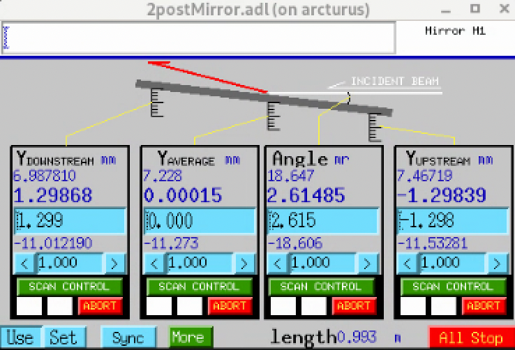
2postMirror.adl — mirror Y / angle control screen. The two
outer columns drive the physical Y motors; the two inner columns
are derived (calc records).
M1 DSY (downstream Y) —
2bma:m2M1 USY (upstream Y) —
2bma:m5Y average — derived (mean of the two Y motors)
Angle [mr] — derived (deflection angle in milliradians, computed from the Y difference and the 0.9932 m mirror length)
These two per-end Y motors and the derived calc records are loaded into the IOC by:
dbLoadRecords("$(OPTICS)/opticsApp/Db/2postMirror.db",
              "P=2bma:,Q=M1,mDn=m2,mUp=m5,LENGTH=0.9932")
i.e. mDn (downstream) = 2bma:m2, mUp (upstream) =
2bma:m5, mirror length 0.9932 m for the angle calc. There are
exactly two physical Y motors on the mirror itself; these are
the operational surface for fine pitch / angle setting via
2postMirror.adl. See the Mirror optical table block below for
why the table-level virtual record (2bma:table1) used to
double-count them and has now been removed.
In-vacuum stripe selector. The mirror has four horizontal coating stripes on its optical surface, selected by translating the mirror laterally with an in-vacuum X stage:
a — 5 nm Pt (single-layer)
b — W(1.2 nm) / Si(5.37 nm) × 50 multilayer (d-spacing 8.8 % below spec)
c — W(1.2 nm) / Si(3.56 nm) × 50 multilayer (d-spacing 10.1 % below spec)
d — W(1.2 nm) / Si(2.73 nm) × 50 multilayer (d-spacing 9.4 % below spec)
Selector motor: 2bma:m3. See the ops page above for the per-
stripe expected-flux curve (mirror_multilayer_coating.png).
Stripe-to-position map (inferred from the live energy2bm.json
store_0 table cross-checked against the Bragg resonance
λ = 2d sin θ at the operational pink-mode mirror angle
m1angl = 2.615 mrad; operator confirmation of the assignments
is pending):
Stripe |
|
Table X ( |
Calibrated Pink energy |
Bragg-calc resonance (or cutoff for Pt) |
|---|---|---|---|---|
a Pt |
1.0 (Mono) 3.039 (Pink 30 keV) |
8.0 / 8.0 |
All 6 Mono energies (held); Pink 30 keV |
Pt critical-angle cutoff at |
b |
13.0 |
10.0 / 10.0 |
Pink 40 keV |
36 keV (slight detuning from 40 keV) |
c |
39.0 |
10.0 / 10.0 |
Pink 50 keV |
49.8 keV (clean match) |
d |
49.0 (requires coordinated table-X move) |
29.0 / 29.0 |
Pink 60 keV |
60.3 keV (clean match) |
In Mono mode (all 6 calibrated energies 13.374 → 25.584 keV)
m3 is held at 1.0 mm — stripe a (Pt) — with table X
at 8.0 mm and mirror angle at 2.615 mrad. The DMM downstream does
the per-energy monochromatic selection; the mirror just deflects
the pink beam onto the DMM at a fixed geometry.
In Pink mode (4 calibrated energies 30 → 60 keV) m3 is
swept per energy, walking up the substrate from stripe a at
30 keV through stripes b / c / d at 40 / 50 / 60 keV.
Table X (m1mox / m1m2x, mapped onto 2bma:m1 and
2bma:m4) is co-moved per energy to extend the substrate’s
useful X range; at 60 keV the table-X support jumps from 10.0 to
29.0 mm to reach stripe d. Mirror angle stays constant at
2.615 mrad across all Pink energies.
The stripe selection is therefore not freely operator-selectable
at run time — the calibration table determines which stripe sits
in the beam at each (mode, energy) tuple, and the energy-change IOC
loads the table value on every energy change. Switching to a
different stripe means either calibrating a new energy at that
stripe via energy add, or manually overriding m3
(operationally rare).
Warning
2bma:m3 does not have enough travel on its own to reach the
highest-energy stripe (d). Reaching that stripe requires a
coordinated move of m3 together with the optical-table X
stages (table X jumps from 10.0 to 29.0 mm at Pink 60 keV per the
table above). This coordination is encapsulated by the
energy-change IOC; see Composite IOCs.
Mirror optical table. The mirror sub-assembly sits on a
multi-motor optical table whose six physical motors live on the
ioc2bma crate as 2bma:m1 through 2bma:m6. The table is
not exposed as a composite virtual record at 2-BM today (the
2bma:table1 record was historically loaded via table.db but
has been removed — see note below). The six physical motors are
driven via two separate, purpose-fit abstractions:
2postMirror.dbfor the mirror’s pitch and vertical translation (the per-end Y motors2bma:m2and2bma:m5); operational surface is2postMirror.adl.The energy-change IOC for the X support motors
2bma:m1and2bma:m4(them1mox/m1m2xper-energy values driven in coordinated moves with the in-vacuum stripe selector to reach the highest-energy mirror stripes; see Composite IOCs).
Per-motor role:
Motor PV |
Role |
|---|---|
|
Table X support, corner 0 (driven by energy-change IOC as |
|
Mirror downstream Y ( |
|
In-vacuum X stripe selector (NOT a table support; see In-vacuum stripe selector block above) |
|
Table X support, corner 2 (driven by energy-change IOC as |
|
Mirror upstream Y ( |
|
Table Z support; present but not used operationally |
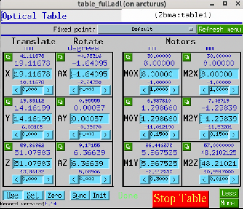
table_full.adl for 2bma:table1, historical screenshot.
This screen showed the table virtual record’s composite axes
while table.db was loaded. As of 2026-06-15 the
2bma:table1 record is no longer loaded (see note below); this
screen will show disconnected PVs at runtime and is kept here for
documentation of the prior configuration only.
Note
History — ``2bma:table1`` virtual record removed 2026-06-15.
iocBoot/ioc2bma/st.cmd previously loaded the synApps
table.db template for this mirror table with the
substitution
"P=2bma:,Q=Table1,T=table1,M0X=m1, M0Y=m2, M1Y=m3, M2X=m4,
M2Y=m5, M2Z=m6, GEOM=SRI"
. That substitution had M1Y =
2bma:m3 — but 2bma:m3 is the in-vacuum X stage that
translates the mirror inside the vacuum chamber (the stripe
selector), not a table Y corner support. The mirror table
physically has only two Y supports (the per-end DSY / USY
motors at 2bma:m2 / 2bma:m5, corroborated by the
2postMirror.db substitution above), so the M1Y slot in
the SRI 3-Y / 2-X / 1-Z template was structural padding
mistakenly filled with the stripe-selector motor record.
Consequence at the time: any move on 2bma:table1.Y, .AX,
or .AY distributed through M1Y and would have perturbed
the in-vacuum stripe selector. The composite Y / pitch / yaw
axes on the table were therefore not safe to drive.
Three resolution paths were considered (tracked at xray-imaging/2bm-docs#171):
Path A — substitute a soft motor record for
M1Yso the composite axes stay nominally functional but no longer touch2bma:m3.Path B — switch to
ASRPmirrorTable.db(the synApps mirror-table-specific template) which usesPITCH+VERTinstead of 6 motors and matches the physical 2-Y geometry.Path C — drop the
2bma:table1virtual record entirely; drive the 6 physical motors directly via2postMirror.db(per-end Y / pitch / vertical) and the energy-change IOC (table X). No composite axes, no soft motor.
Path C was chosen (operator-confirmed 2026-06-15): the
dbLoadRecords line for table.db was commented out in
iocBoot/ioc2bma/st.cmd, so the 2bma:table1 record and
its .X / .Y / .Z / .AX / .AY / .AZ composite axes no longer
exist in CA. All operational motion at the mirror goes through
2postMirror.db (pitch / vertical) and the energy-change IOC
(table X for stripe-selector extension); 2bma:m6 (the Z
support) remains an addressable raw motor record but is not used
operationally.
Double Multilayer Monochromator (DMM)
- Role:
Energy selection (monochromatic mode)
- Family:
Monochromator (listed as “Pending in code” in the cora Equipment BC families catalog at
docs/catalog/families.md; not yet a registered Family. Two crystals — upstream (US) and downstream (DS) — each with X / Y / Bragg-arm drives, plus global tank Y / Z. Upstream crystal carries a split Y (OB / IB) for combined Y translation and Z-tilt.)- Mounted on:
Front-end stand (floor-referenced)
- Carries:
(beam conditioning only)
- z position:
crystal 1 at 29335 mm, crystal 2 at 29934 mm (ref 2: centre of optic)
- Y offset:
9.0 mm (crystal 1), 41.0 mm (crystal 2)
- Position tolerance:
250 µm (x, y), 5 mm (z)
- Material:
Silicon
- Inter-crystal spacing:
1323 mm along beam, 765 mm in/out-board (read from screen)
- Reference (ops):
https://docs2bm.readthedocs.io/en/latest/source/ops/item_021.html#dmm
- MEDM screen:
DMMV.adl(running onarcturus)- EPICS prefix:
2bma:(motors listed below)
Insertable: white-beam operation bypasses the DMM. Energy-change coordination across the DMM motors and the mirror stripe selector is encapsulated by the energy-change IOC; see Composite IOCs.
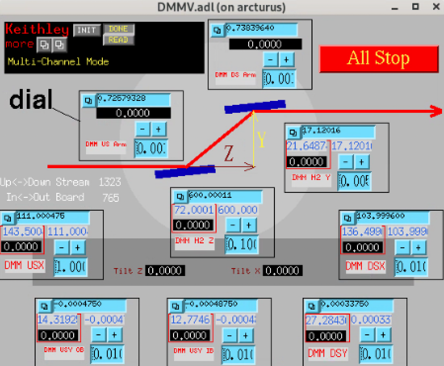
DMMV.adl — DMM control screen.
Motors:
Description |
Role |
EPICS PV |
|---|---|---|
DMM M2 Z |
Second crystal translation along the beam relative to the first |
|
DMM USX |
Global tank upstream X |
|
DMM USY OB |
Global tank upstream Y outboard side |
|
DMM USY IB |
Global tank upstream Y inboard side |
|
DMM DSX |
Global tank downstream X |
|
DMM DSY |
Second crystal Y relative to the first |
|
DMM US Arm |
Upstream Bragg-arm rotation |
|
DMM DS Arm |
Downstream Bragg-arm rotation |
|
DMM M2 Y |
Second crystal Y (companion to |
|
The tank’s upstream end carries two independent Y motors (USY OB
and USY IB); their average sets the upstream tank Y position and
their difference produces a Z-tilt around the beam axis. The second
crystal is positioned relative to the first via the DSY (Y),
M2 Z (along beam), and M2 Y motors.
Tank / alignment motors (energy-independent within mode). The
five DMM tank-positioning motors (2bma:m25-m29) are part of the
energy-change coordinated move but do NOT vary per energy; they take
only two configurations selected by mode:
Motor |
PV |
Mono (in beam) |
Pink (out of beam) |
Role |
|---|---|---|---|---|
|
|
111.0 |
111.0 (same) |
Upstream tank lateral X — fixed alignment (NOT a stripe selector; the value is identical in Mono and Pink) |
|
|
0.0 |
-10.0 |
Upstream tank Y outboard — in-beam vs retracted |
|
|
0.0 |
-10.0 |
Upstream tank Y inboard — in-beam vs retracted |
|
|
104.0 |
104.0 (same) |
Downstream tank lateral X — fixed alignment (NOT a stripe selector) |
|
|
0.0 |
-10.0 |
Downstream tank Y — in-beam vs retracted |
The X pair (m25 / m28) is the same lateral position in both
modes — they are not the per-energy stripe selector. The
per-energy mirror-stripe selection is on the Mirror M1 (see
m1_horizontal (2bma:m3) in the M1 block). The three Y motors
swing the DMM tank into or out of the beam at mode switch.
The IOC re-asserts these values on every energy change (they’re in
the energy_move_* set in energy2bm.json), but interpolation
between the two constant values per axis is degenerate — the
result is the constant. This answers cora ENERGY-5.
DMM substrate carries two multilayer stripes (full specs in
DMM: 13.8 Å and 24 Å multilayer periods, 4 mm
apart laterally, 140 x 44 mm² each, W-B₄C on Si). Across all six
calibrated Mono energies, applying Bragg’s law (λ = 2d sin θ) to
the saved Bragg-arm angles yields d ≈ 24 Å to within ~5%, with no
values near 13.8 Å — so the 24 Å stripe is the currently active
one at 2-BM. The 13.8 Å stripe has never been calibrated into
energy2bm.json; switching to it would be a 4 mm lateral
substrate move (the candidate axis is m25 or m28, since the
substrate geometry matches the 4 mm stripe spacing, but the actual
mapping needs operator confirmation) plus a separate Mono-mode
recalibration of the Bragg arms and M2 Y for the new stripe.
This answers cora ENERGY-6.
Per-energy saved positions (energy-tracking subset). The energy-
change IOC drives three of the DMM motors per energy: the two Bragg
arms (2bma:m30 / 2bma:m31) and the second-crystal vertical
(2bma:m32). Values are stored in
energy2bm.json
under the store_0 field of each motor; the IOC reads them on each
energy change. Reproduced here as a snapshot (the JSON file is the
authoritative source):
Mode |
Energy [keV] |
|
|
|
|---|---|---|---|---|
Mono |
13.374 |
1.131 |
1.133 |
25.1201075 |
Mono |
13.574 |
1.081 |
1.083 |
24.3201075 |
Mono |
18.000 |
0.822 |
0.824 |
18.820045 |
Mono |
20.000 |
0.726 |
0.737 |
17.020045 |
Mono |
25.000 |
0.57725 |
0.58825 |
14.220045 |
Mono |
25.584 |
0.561 |
0.572 |
13.920045 |
Pink |
30 / 40 / 50 / 60 |
0.740 (parked) |
0.751 (parked) |
17.020045 (parked) |
The Pink-mode values are constant across all four configured energies
(30 / 40 / 50 / 60 keV) — the Bragg arms are simply retracted to a
fixed park position and m2_y is held at the same value it had at
the Mono 20 keV configuration. The other five DMM motors
(2bma:m25–m29) also have store_0 entries — in Pink the Y
motors (USY OB / USY IB / DSY) are driven to -10 mm
to take the DMM out of beam — but those are not what cora’s ENERGY-1
question asks about. This table answers cora ENERGY-1.
Flag (diagnostic phosphor)
- Role:
Diagnostic phosphor screen on a vertical stage. A visible- light camera looks at it so operators can see the X-ray beam position and gauge intensity. In pink-beam (white-beam) mode the flag is parked at its lower limit (
Y = 0 mmuser,5 mmdial) – out of the beam. In mono mode the flag is raised to block the M1-scattered halo while letting the monochromatic beam pass; the exact Y is energy-dependent.- Family:
Screen(cora-confirmed).- cora Asset:
DiagnosticFlag, mounted onFrontEndDrive(the front-end OMS VME58 #1). Operator-raised in Mono mode (Y position is energy-dependent, see table below) and parked at the lower limit in Pink mode. The energy-tracking Y curve is the lookup-table data answering cora FLAG-1.- Mounted on:
Own stand in 2-BM-A (floor-referenced).
- Carries:
phosphor-painted flag + visible camera (not modelled here; the camera is its own Asset).
- z position:
32500 mm (between the DMM and the P6-50 safety shutter). Not separately listed in the APS reference table.
- EPICS:
2bma:m44– single vertical (Y) motor.- User/dial offset:
user = dial - 5 mm. Limits (user, from
meters_all.adl): -4.5 to +35.0 mm (dial 0.5 to 40.0 mm).
The energy-dependent flag positions used by mono-beam scans are
defined in the energy package’s lookup table
(energy2bm.json,
key energy_move_flag):
DMM energy keV |
Flag Y (mm, user) |
Comment |
|---|---|---|
13.374 |
23.0 |
highest (low energy) |
13.574 |
22.0 |
|
18.000 |
17.0 |
|
20.000 |
15.0 |
|
25.000 |
12.0 |
|
25.584 |
12.0 |
|
30.000 |
0.0 |
flag down (out of beam) |
40.000 |
0.0 |
|
50.000 |
0.0 |
|
60.000 |
0.0 |
highest energy |
Pink-beam mode: flag at Y = 0 mm (user) – same as the
“flag down” position used by mono at 30 keV and above.
Note
Procedures that command this component.
Move flag into beam (mode-dependent) (set_flag_in) is the stub
that satisfies the flag_in_beam precondition of
Detector Z-rail alignment to the beam (detector_z_rail_alignment).
The energy-dependent target Y is read from the
energy_move_flag field of energy2bm.json;
operating in
pink mode means writing 0 mm user to 2bma:m44.
2-BM-A alignment camera (FLIR Oryx 5MP)
- Role:
Beamline-alignment diagnostic camera that images the white, pink, or monochromatic beam at the 2-BM-A end. Used during the white-beam centring + mirror / DMM alignment procedure (see Beamline alignment and Beamline alignment (white -> pink -> mono)).
- Family:
Camera (a second instance of the cora
CameraFamily; the per-microscope detectors at 2-BM-B are the other instances).- cora Asset:
proposed
AStationAlignmentCamera(cora has not chosen a handle yet; the role-name convention “Camera named by what it images” would also work asWhiteBeamAlignmentCamera).- Hutch:
2-BM-A.
- Mounting:
Permanently installed at 2-BM-A on a stand with a single vertical (Y) motor for beam-finding. Semi-permanent diagnostic — the camera is always in place, but the beam only reaches it when the upstream vacuum chamber is opened and a pipe section is physically removed. This is a multi-hour operation done only rarely (annual / multi-year cadence, typically for major realignment after a long shutdown or major optics intervention). The setup is kept installed for convenience because the disassembly / reassembly time is nontrivial.
- Camera model:
FLIR Oryx 5MP (inferred from the IOC startup script name
2bmbOryx5MP; same camera-family as the microscope-camera-0 at 2-BM-B but a distinct physical unit). Operator confirmation of the exactORX-10G-51S5Mmodel number is pending.- Vertical-stage motor:
2bma:m21(single Y axis used for beam-finding during alignment; positioned in the beam path by the alignment procedure, returns to a parked Y between uses).- IOC:
2bmbOryx5MPrunning on host lyra (a 2-BM-B workstation per Computing; physically remote from the camera in 2-BM-A but addresses it via the network). Start sequence (per Beamline alignment):(base) 2bmb@lyra ~ $ 2bmbOryx5MP medm (base) 2bmb@lyra ~ $ 2bmbOryx5MP run
- EPICS prefix:
TBD (not separately documented; accessible through the IOC name above. Operator confirmation pending whether the areaDetector prefix is
2bmA:/2bma:/ something else).- Live viewer:
ImageJ with the EPICS_NTNDA plug-in is the standard operator surface during alignment;
ImageJinvoked from lyra.
Note
Why this is documented as a permanent inventory entry, not a
transient diagnostic. The cora ALIGN-1 question explicitly
asks whether this is a standing diagnostic or a temporary
setup brought in only for alignment. The operationally correct
answer is semi-permanent: physically installed all the
time, but the beam only reaches it when an operator manually
breaks vacuum and removes a pipe. So it belongs in the cora
inventory as a registered Camera Asset (not a temporary /
transient fixture), with the understanding that its
operational-availability state is “deployed but not engaged”
most of the time. This answers cora ALIGN-1.
P6-50 Safety Shutter (B-shutter)
- Role:
Personnel-safety shutter for 2-BM hutches
- Family:
Shutter (already registered as the cora
StationShutterAsset (coraShutterFamily) indocs/deployments/2-bm/assets.md; this entry is the source of its position and shielding data.StationShutteris the role-name cora chose for the B-station personnel-safety shutter; the upstream A-shutter would be a separateShutterAsset — see the A-shutter block above.)- Mounted on:
Front-end stand (floor-referenced)
- Carries:
(beam gating only)
- z position:
33343 mm (ref 1: upstream face of thermal component)
- Position tolerance:
250 µm (x, y), 5 mm (z)
- Material:
W [21 mm]
- Aperture:
60.0 × 44.5 mm
- RSS tag:
part of 02-BM-A-P-01 assembly
- Reference drawing (shutter element):
41050401-410003- Reference drawing (full P6-50 assembly):
41050401-500000(covers all four elements: white-beam stop41050401-300001, W collimator41050401-500001, safety shutter41050401-410003, SS baffle41050401-500200). Source: APS_2191941 row 10. Answers cora BEAM-3.- EPICS prefix:
S02BM-PSS:SBS- Open command:
S02BM-PSS:SBS:OpenEPICSC- Close command:
S02BM-PSS:SBS:CloseEPICSC- Status readback:
S02BM-PSS:SBS:BeamBlockingM(DBF_ENUM, read-only; descriptionSBS BLEPS Status; hosted on the PSS gateways2pvgate). The status is reported via BLEPS rather than the PSS directly.STATE 0 =
OFF→ beam is not being blocked → shutter OPEN.STATE 1 =
ON→ beam is being blocked → shutter CLOSED.
Same inverted semantics as the A-shutter
BeamBlockingMPV above: the readback reports the blocking state, not the shutter position. After issuingOpenEPICSC/CloseEPICSCconfirm by readingBeamBlockingM.- Notes:
One element of the four-component P6-50 stack (white-beam stop, tungsten collimator, safety shutter, SS baffle) installed together at z ≈ 330 m. The other three are passive. Both this and the upstream A-shutter must be open for beam to reach 2-BM-B.
Note
The “fast shutter” in TomoScan / 2-BM operator parlance IS this P6-50 SBS shutter. There is no separate pneumatic / fast-actuator shutter at 2-BM-B today; the P6-50 is the beam-gate that closes for dark and white (flat) field acquisition during every scan. The upstream A-shutter (FES) is kept open continuously to preserve the thermal stability of the beamline optics, so the per-scan gating responsibility falls on the P6-50.
TomoScan wiring (intended). Both TomoScan shutter macro pairs target the same P6-50 SBS shutter:
TomoScan macro / method |
Target PV |
|---|---|
|
|
|
|
|
|
|
|
|
|
|
|
|
|
|
|
|
|
Both macro pairs map to the same physical shutter because there
is only one EPICS-controllable beam gate at 2-BM-B today. The
FES (S02BM-PSS:FES:) is read-only from TomoScan’s
perspective via S02BM-PSS:FES:FEEPSPermitM (the
BEAM_READY macro), and stays open throughout the session.
Despite the frontend in the open_frontend_shutter method
name, the actual PV target is the B-station P6-50, NOT the
upstream FES. Misleading; tangential to fix.
Substitutions-file caveat (pending fix). The current
iocBoot/iocTomoScan_2BMB/tomoScan.substitutions correctly
binds the OpenShutter / CloseShutter pair to the SBS
PVs above, but the OpenFastShutter / CloseFastShutter
pair is bound to stale placeholder soft PVs
(2bma:B_shutter:open.VAL / close.VAL) that have no
physical actuator behind them. The TomoScan2BM.open_shutter()
/ close_shutter() methods accordingly log
"Wait 2s -- Temporarily while there is no fast shutter at
2bmb"
and just time.sleep(2). The substitutions file
will be updated to point OpenFastShutter / CloseFastShutter
at the SBS PVs as well; the 2-second sleep can then be removed
from the TomoScan methods (the P6-50’s own actuation time
becomes the only physical delay).
Operational consequence: during a TomoScan run the P6-50 cycles open / close many times per scan (closed for darks and for flat-fields, open for projections); this is by design, not a shutter failure. Cycle counts can be high.
B-station Slits
- Role:
Beam-shape conditioning at the 2-BM-B entrance, ~21 m downstream of the front-end L3 slits
- Family:
Slit (same standard APS L3-20 four-blade hardware as the front-end L3 Slits; reuses the
SlitFamily declared there. No filter changer is paired with this assembly.)- cora Asset:
SampleSlit(proposed name; not yet registered. Used as thetarget_asset_idsvalue bycalibrate_slit_blade_throw(Calibrate the throw of each L3 slit blade motor) and bycentre_and_close_slits(Centre and close an L3-style slit aperture).)- Mounted on:
Own stand in 2-BM-B (floor-referenced)
- Driven by:
FrontEndDrive(same OMS VME58 board as the A-station L3 Slits, despite the B-station mounting location — the IOC crate is in 2-BM-A and addresses both stations’ slits over VME)- Carries:
(beam conditioning only)
- z position:
50500 mm (read from layout drawing A342-RT1000-02; not listed in the APS_1404611 reference table)
- Position tolerance:
250 µm (x, y), 5 mm (z) (assumed identical to the A-side L3 Slits)
- MEDM screen:
2slit.adl(same screen layout as the A-side slits, instantiated with the B-blade motor PVs)- EPICS prefix:
2bma:(horizontal motors2bma:m11and2bma:m12for the X pair; vertical motors2bma:m9for Y+ [up] and2bma:m10for Y− [down])- Virtual motor PVs:
the four composite Size/Centre
ao-record PVs below drive both blades of a pair together. Hosted onioc2bmb1.xray.aps.anl.gov:5064(the same IOC that hosts the A-station slit calc records, despite the2bma:prefix on both). These are the PVs the2slit.adlMEDM screen wires to theSizeandCentertext-entry boxes; theSize/Centervalues you set on the screen propagate through downstream calc records to the individual blade motors.PV
Limits (mm)
2bma:Slit2Hsize+45.50 / -112.50
2bma:Slit2Hcenter+37.08 / -41.92
2bma:Slit2Vsize+115.62 / -34.13
2bma:Slit2Vcenter+52.28 / -22.60
(Earlier doc attempts referred to
2bma:Slit2H:sizewith a colon — that is NOT the name. The canonical names are no-colon concatenations as listed.)- Notes:
These are the slits driven by
b_slit_top(=2bma:m9) andb_slit_bot(=2bma:m10) in the energy-change IOC; the vertical pair tracks the per-energy beam position in Mono mode. See Composite IOCs.
Per-energy vertical positions. The energy-change IOC drives the
vertical pair (2bma:m9 / 2bma:m10) per energy to follow the
DMM beam-walk; the horizontal pair (2bma:m11 / 2bma:m12) is
NOT energy-tracked. Values from
energy2bm.json
store_0:
Mode |
Energy [keV] |
|
|
|---|---|---|---|
Mono |
13.374 |
28.804575 |
8.804575 |
Mono |
13.574 |
28.804575 |
8.804575 |
Mono |
18.000 |
28.804575 |
8.804575 |
Mono |
20.000 |
31.144575 |
11.144575 |
Mono |
25.000 |
26.23 |
6.23 |
Mono |
25.584 |
26.28 |
6.28 |
Pink |
30 / 40 / 50 / 60 |
10.0 (wide open) |
-10.0 (wide open) |
Mono-mode top/bottom values track each other (top − bottom ≈ 20 mm across all six configured energies); the slit aperture stays roughly constant while the pair’s centre tracks the beam-walk. Pink-mode is constant across all four energies (slits parked wide open at +10 / -10 mm; no per-energy tracking because the DMM is bypassed). This table answers cora ENERGY-2.
Note
Horizontal-blade label flip. The horizontal blade labels on
the operator side (“B slit Inb” / “B slit outboard”) are
flipped with respect to the physical inboard / outboard
direction: the detector image is mirrored left / right, so the
on-screen “inboard” actually drives the outboard physical blade
and vice versa. The mapping of 2bma:m11 and 2bma:m12 to
the X+ / X− blades follows the physical convention (positive X
outboard), not the on-screen labels.
2slit.adl (2-BM-B instance) — horizontal-slits control screen
(“LOOKING UPSTREAM”, Lab coordinate system). The two leftmost
columns (Slit2H − / Slit2H +) drive the individual blade
motors 2bma:m11 and 2bma:m12. See the label-flip note
above. The Size and Center columns are calc-driven
composites that move both blades together to set the aperture
width and centre.
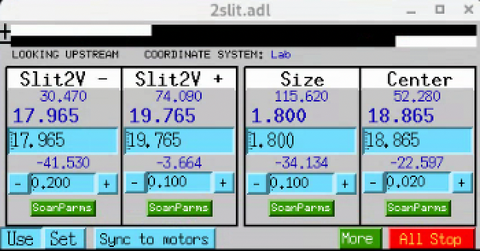
2slit.adl (2-BM-B instance) — vertical-slits control screen
(same layout as the horizontal screen). The two leftmost columns
drive the individual blade motors: 2bma:m9 for the Y+ blade
(up, screen-labelled Slit2V +) and 2bma:m10 for the Y−
blade (down, screen-labelled Slit2V −). The Size and
Center columns are calc-driven composites.
Note
cora Asset registration intent. When the Slit Family
graduates from Pending, register this assembly as Asset
SampleSlit with the same structure as the proposed
ConditioningSlit Asset (see L3 Slits block above) but
with the B-station PV set:
Family:
SlitMounted on: own stand in 2-BM-B (floor reference)
controller_id back-reference:
FrontEndDrive(the IOC crate is in 2-BM-A and addresses both stations’ slits over VME; both A and B Slit Assets back-reference the same controller)Settings (blade motors):
2bma:m11and2bma:m12(H pair, per the label-flip note above),2bma:m9(V+ up),2bma:m10(V− down)Settings (virtual / calc-driven aperture):
2bma:Slit2Hsize,2bma:Slit2Hcenter,2bma:Slit2Vsize,2bma:Slit2Vcenterz position: 50500 mm (read from layout drawing A342-RT1000-02; not in the APS_1404611 reference table)
Per-blade calibration field
calibration_slope_pix_per_mm(one per blade motor), seed values + conditions from the Calibrate the throw of each L3 slit blade motor field-test table for the “B station (no fix needed)” run (2026-06-14).Target of Procedure
calibrate_slit_blade_throw(Calibrate the throw of each L3 slit blade motor) and Procedurecentre_and_close_slits(Centre and close an L3-style slit aperture).
Coded aperture (Jena NV200D piezo)
- Role:
Beam-shaping coded aperture mounted in the beam between the B-station Slits and the sample. The aperture is stepped through a list of (X, Y) piezo positions during a tomography fly-scan to produce randomised / dithered sampling for compressive-sensing imaging reconstructions.
- Family:
(Pending — neither Camera nor Stage in the traditional sense; the mask itself is a beam-path optical element with its own positioning piezo; cora’s eventual Family choice for the mask is a separate decision from the piezo controller below.)
- cora Asset:
CodedApertureFineDrive(piezo-controller Asset; proposed name;SampleFineDrivewas the earlier provisional placeholder and is wrong — the device does not move the sample). Family:MotionController. Operator-confirmed 2026-06-19. The earlier provisionalOpticsFineDriveplaceholder for the unused NV100D (see Jena NV100D) should be retired since the NV100D is not in operational use at 2-BM.- Hutch:
2-BM-B
- z position:
~51,300 mm (between the B-station Slits at 50,500 mm and the sample stack; just downstream of the last Be window before 2-BM-B)
- Hardware (controllers):
Two Piezosystem Jena NV200D/NET controllers, one per piezo axis (not a single dual-channel controller). Each is Ethernet-attached and addressed via the vendor’s Telnet interface on port 23 (“NV200/D NET>” prompt):
Axis
Controller IP
Vendor model
X
10.54.113.126NV200D/NET
Y
10.54.113.125NV200D/NET
Vendor datasheet: NV200D-Datasheet.pdf.
NOT the NV100D (which lacks the external trigger mode required for tomoscan fly-scan integration and is therefore not used at 2-BM in any operational procedure today; see Jena NV100D for the NV100D historical / decommissioned reference).
- Actuator:
Piezosystem Jena XY flexure stage, nanoSXY 120 CAP, part number T-223-06D (the “D” suffix denotes the digital interface variant). Drawing: nanoSXY-120-CAP (rev.01, Feb 2019). Key dimensions:
Property
Value
Travel per axis (nominal)
120 µm
Travel per axis (closed-loop, per Jena NV200D)
100 µm
Clear aperture
Ø 12.5 mm (centred)
Outer footprint
82 × 79 × 30 mm
Mounting
4× M3 tapped + 4× Ø3 G7 reamed dowel holes (symmetric, on both sides); 32 mm / 54 mm / 60 mm hole-pattern centres
Standard cable length
1600 mm (voltage + sensor cables)
Feedback
Capacitive (the
CAPin the model)The clear aperture is what the coded-aperture mask itself is mounted into; the X / Y piezo motion moves the mask within the beam.
- IOC:
JenaNV200D(running onarcturus)- Operational reference:
Jena NV200D covers IOC startup, network configuration, caQtDM screens, FPGA trigger integration, and the triggered-step mode.
- Programming procedure:
Triggered-step buffer programming, formal procedure page NV200D triggered-step buffer programming (slug
nv200_trigger_step). Implementation lives in the2bm-proceduresrepository at procedures/nv200_trigger_step.py (official nv200 Python library-based; runs the per-axis setup concurrently viaasyncio). Loads a 1024-position-max waveform buffer into each controller via Telnet and arms the FPGA-trigger-driven advance.A second variant lives in the sandbox at
/home/beams/2BMB/conda/sandbox/nv200/nv200_trigger_step.py— raw Telnet, nonv200library; documents the vendor’s command vocabulary directly (gparb,gsarb,gearb,goarb,gtarb,gcarb,trgfkt,2,modsrc,3,grun,gsave/gload,meas,posmin/posmax,cl). Kept as a reference implementation of the protocol; not the operationally-blessed script.Defaults to
n = 256positions per axis (max 1024) and takes a--randomflag for randomly-sampled positions (default is evenly-spacedlinspace). After each generation the positions are saved topositions_x.txtandpositions_y.txtin the current working directory. Current operational state (as of late 2026) uses--randomfor compressive-sensing dithered sampling during tomography fly-scans.Operational constraint: each controller only accepts one Telnet connection at a time, so the EPICS IOC must be stopped before running the script (and restarted afterwards). The triggered-step state can optionally be persisted to EEPROM via the script’s
save_to_eeprom()so it survives a power cycle.
Note
Why this lives here (between B-station Slits and Sample
stack). The coded aperture is a beam-path element upstream of
the sample, not part of the sample tower. Putting its description
in the z-ordered walk between B-station Slits (50,500 mm) and the
Sample stack section below matches the physical layout. The
piezo controller (CodedApertureFineDrive) is the
MotionController Asset that drives the aperture mask, but the
mask itself is a separate beam-path element — cora’s eventual
Asset model needs both.
Sample stack
The sample tower is a kinematic chain of six elements, from the experimental-hutch floor up to the sample itself. Order matters: stages below the rotary translate or tilt the rotation axis in lab coordinates; stages above the rotary ride with the sample and appear in projection space.
Kinematic chain (bottom to top):
Sample optical table              (Y only; floor-referenced)
  +-- Hexapod                  (6-DOF coarse positioner)
       +-- LaminographyPitch        (laminography pitch, 0-20 deg)
            +-- fixed -10 deg wedge (cancels +10 deg stage hold)
                 +-- Rotary  (theta axis)
                      +-- SampleTop_X     (co-rotates with theta)
                      +-- SampleTop_Z     (co-rotates with theta)
Note
The cora 2-BM asset inventory at
docs/deployments/2-bm/assets.md lists four sample-top
Devices: SampleTop_X, SampleTop_Z,
Sample_top_Roll, Sample_top_Pitch.
SampleTop_X and SampleTop_Z are the Kohzu CYAT-070
stages above the rotary and are documented below.
Sample_top_Roll and Sample_top_Pitch correspond to the
hexapod’s Roll (2bmHXP:m5) and Pitch (2bmHXP:m4) axes —
they are part of the Hexapod block below, not separate
per-component stages above the rotary. cora classifies these
two as PseudoAxis Assets (“virtual DoFs over the 2bmHXP
hexapod-kinematics solver”), confirming the same mapping.
Note
For cora PV mapping. Every 2bmb:mNN PV cited in the
Sample stack and Detector system sections has been verified
against the ioc2bmb IOC: OMS-VME58 motors m1–m91 are
declared in motor.substitutions, and the Aerotech Ensemble
axes m100/m101/m102 in AsynMotor.substitutions
(asyn ports AeroE1/AeroE2/AeroE3). The motor records
themselves carry generic DESC strings ("motor $(N)"), so
the per-Device role (e.g. SampleTop_X = 2bmb:m18) is not
recoverable from the IOC alone — it is configured in mctoptics
substitutions, tomoScanStream, table.db calls, and this
page. When registering cora Devices against ioc2bmb PVs, treat
this page as the source of truth.
Sample optical table
- Role:
Floor-referenced support for the entire sample tower
- Family:
Table (cora
TableFamily, declared in the cora catalog atcatalog/catalog.yamland pending registration as AssetSampleTableindocs/deployments/2-bm/assets.md. The substrate word “Optical” is deliberately omitted from the Family name per cora’s naming rule that a Family names the device’s own nature, not its contents — theOpticalHousing→Housingprecedent. Axis-set differences across the three 2-BM tables (sample = 4 direct translation motors; detector = 6 virtual axes; mirror = present but unused) are a per-Asset settings axis (axis_layout), not a Family split.)- Mounted on:
Hutch floor
- Carries:
Hexapod (and everything above)
- Degrees of freedom:
4 motors (Y, downstream X, upstream X, Z). In routine operation only Y is moved; the X and Z motors exist but are not used for day-to-day sample positioning.
- EPICS:
Axis
PV
MEDM label
Y (vertical)
2bmb:m24Sample table YZ
2bmb:m20Sample table ZUSX
2bmb:m21Sample table USX(upstream X)DSX
2bmb:m22Sample table DSX(downstream X)No combined
table.dbvirtual record is loaded for this table — the four motors are addressed directly.- Notes:
Used to set a coarse vertical origin so the hexapod operates near the centre of its Y travel. Standard APS optical-table hardware on a Vibraplane isolation base (visible in the sample-stack photo below).
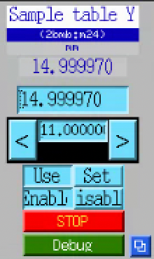
Single-motor stage-control screen for the Y axis (2bmb:m24).
This is the screen used for routine vertical positioning of the
sample tower — no aggregating table MEDM is needed since only one
axis moves in normal operation.
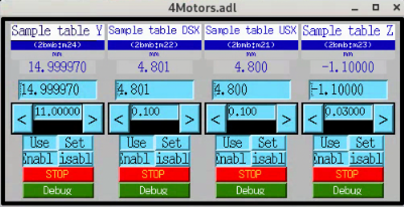
4Motors.adl MEDM for all four axes of the sample optical
table (Y, DSX, USX, Z), shown for reference when the rarely-used
X or Z axes need to be touched.
Hexapod
- Role:
Coarse 6-DOF sample positioner
- Family:
Hexapod
- Model:
Aerotech HexGen HEX300-230HL hexapod (300 mm platform, 230 mm home height). Full ordering code: HEX300-230HL with suffixes
-E1(incremental encoders),-PL4(ULTRA high-accuracy performance grade) and-TAS(tested and integrated as a system).- Serial number:
486060-01- Mounted on:
Sample optical table
- Carries:
LaminographyPitch
- Driven by:
HexapodDrive(coraMotionControllerAsset, bound to Aerotech Automation1-iXR3 drive, full ordering codeAutomation1-iXR3-VL1-VB4-VB4-SB0CT222222-P1P1P1P1P1P1-CO-LC1MT1PSO6-SI0-TAS, S/N486125-01, in a separate rack; operator-confirmed 2026-06-15. Earlier this page noted “specific product line not yet confirmed”; this is the resolution.)- Degrees of freedom:
X, Y, Z, A (θx), B (θy), C (θz)
- Travel:
X 55 mm, Y 60 mm, Z 25 mm, A 15°, B 15°, C 30° (single-axis moves from home; travels are mutually exclusive — consult Aerotech’s HexGen workspace simulator for combined-move envelopes)
- Resolution:
20 nm (XYZ), 0.2 µrad / 0.04 arc-sec (ABC)
- Accuracy:
±1 µm (X), ±0.75 µm (Y, Z), ±10 µrad / ±2.1 arc-sec (A, B, C); PL4 ULTRA grade, measured over full travel.
- Maximum speed:
50 mm/s (X), 25 mm/s (Y, Z), 15 °/s (A, B), 30 °/s (C)
- Load capacity:
45 kg vertical, 21 kg horizontal, 14 kg de-energized holding; stage mass 12 kg
- Drive:
Precision ball screw, brushless slotless servo, 80 VDC bus
- EPICS:
Prefix
2bmHXP:. Per-axis motor records (only the user-accessible axes are exposed):Axis
PV
Notes
X
2bmHXP:m1linear, lab-X
Y
2bmHXP:m2linear, lab-Y (vertical)
Pitch
2bmHXP:m4rotation about lab-X
Roll
2bmHXP:m5rotation about lab-Z (beam axis)
2bmHXP:m3(Z) and2bmHXP:m6(Yaw / θz) are not exposed to the user.m3is reserved for the MCTOptics IOC, which drives it asLENS_SAMPLE_Yfor sample-side Y alignment relative to the microscope.Top-level launcher screen is the
2bmHXPUI (seehexapod_01.png); native Aerotech Ensemble interface rather than plain motor records.- Notes:
Coarse positioning of the entire sample tower. Y is shared with the optical table: convention is to set table Y so the sample sits in the beam with the hexapod at mid-travel, maximising remaining hexapod DOF for fine alignment. See the Hex300-230HL data sheet (
Hex300-Data-Sheet-D20250203.pdf) for accuracy maps and load curves.
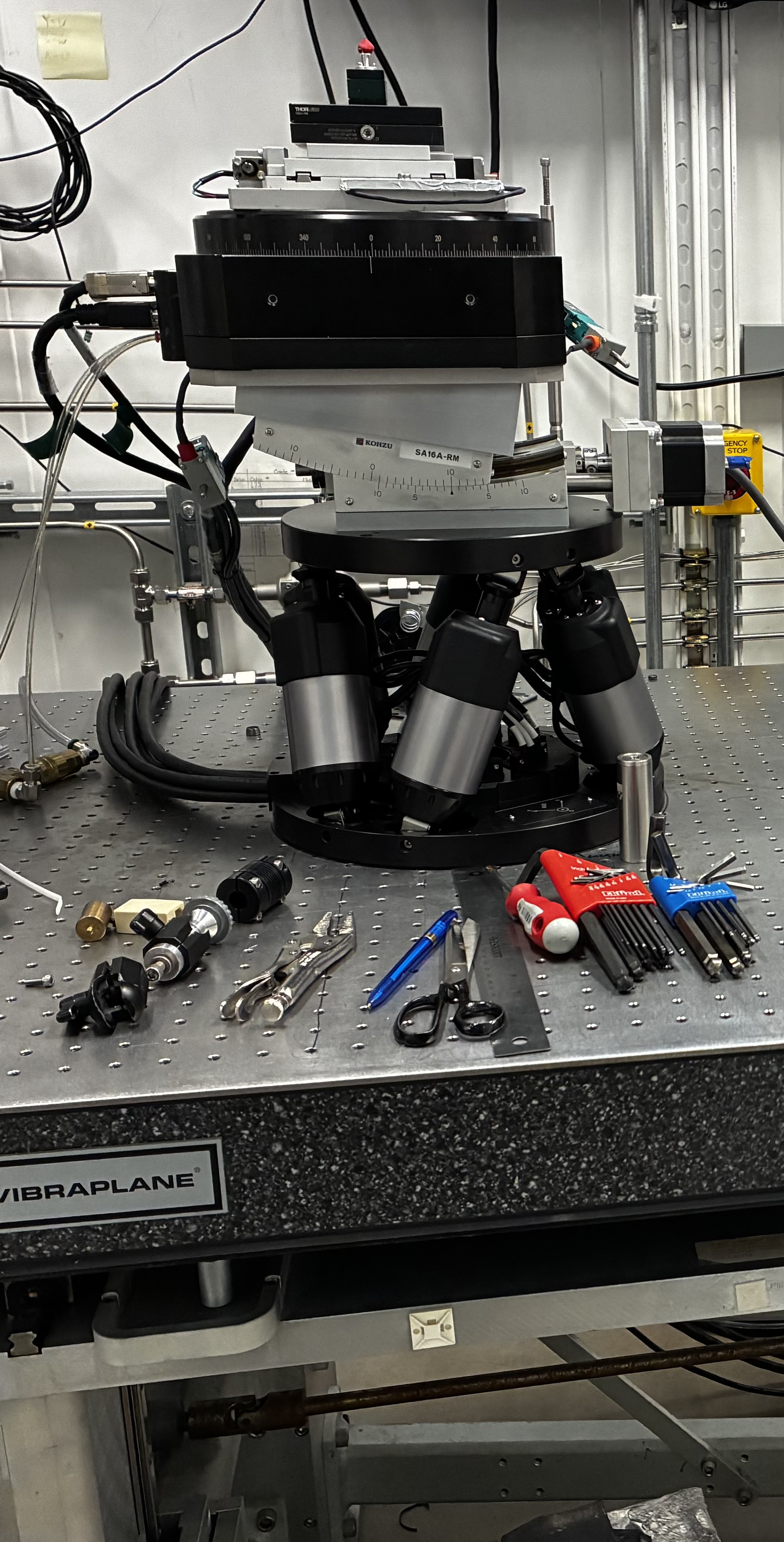
2-BM-B sample stack on the Vibraplane-isolated optical table. Visible from bottom to top: the Aerotech HEX300-230HL hexapod (six struts), the Kohzu SA16A-RM laminography tilt stage (centre), and the Aerotech ABRS-250MP-M-AS air-bearing rotary at top.
LaminographyPitch
- Role:
Laminography pitch axis
- Family:
TiltStage (cora
TiltStageFamily, declared specifically for the Kohzu SA16A-RM laminography goniometer perdocs/deployments/2-bm/assets.md: a rotational, limited-range stage — so neitherLinearStagenorRotaryStage(whoseFollowing/MarkingPSO affordances a tilt does not carry). Affordances:Rotatable,Homeable,Limitable. Not yet instantiated as an Asset; the closest pending entry is “Broader sample-stage motors” in that page’s Pending table.)- Model:
Kohzu SA16A-RM goniometer / tilt stage
- Mounted on:
Hexapod
- Carries:
Rotary (via a fixed -10° wedge)
- Travel:
0° to 20° (full mechanical range; see operating convention below)
- EPICS:
2bmb:m49- Notes:
Inserted between the hexapod and the rotary specifically for laminography. A fixed -10° wedge sits between this stage and the rotary; the stage is held at +10° so the two cancel and the rotation axis is vertical (standard tomography). Sweeping the stage between 0° and 20° therefore gives a ±10° (20° total) range of net rotary-axis tilt for laminography. The default laminography setpoint is +15° on the stage, i.e. +5° net rotary-axis tilt.
Rotary
- Role:
Sample rotation axis (theta)
- Family:
RotaryStage
- Model:
Stage — Aerotech ABRS-250MP-M-AS air-bearing direct-drive rotary (Aerotech ABRS series, 250 mm aperture, mid-precision class). Drive — Aerotech ENSEMBLE ML 10-40-IO-MXH (Multi-Loop subseries, 10 A, 40 V bus, I/O option, MXH option; operator-confirmed against the hardware label 2026-06-16). The cora Device identifier
Rotaryis a role-name per cora’s #111 convention (vendor / model lives in the bound Model, not the Asset name). Earlier candidate names:Aerotech_ABRS_rotary,aerotech_abs250mp_m_as— the second one was based on a then-incorrectABSreading of the hardware label; operator confirmation 2026-06-15 settles the model on ABRS.- Serial number:
146853-A-1-1-X- Reference drawing:
630C2125 REV (-)- Mounted on:
LaminographyPitch (via a fixed -10° wedge — see above)
- Carries:
SampleTop_X, SampleTop_Z
- Driven by:
RotaryDrive(coraMotionControllerAsset wrapping the Aerotech ENSEMBLE ML 10-40-IO-MXH, S/N730792/1, Aeronet-networked. Earlier this page named the drive as Ensemble HLE10-40-A-MXH; operator confirmation 2026-06-16 corrects both the subseries (ML, not HLe) and the option suffix (-IO-was missing). The drive card is housed in an Aerotech TM3-A-20B VDC-20B VDC / NO SPLIT / PS24-1 / C1ML-06 / C2ML-09 / US-115VAC chassis, S/N160591-A-1-1(Order #730578, built to dwg630D2079 REV-H); the chassis + PS24-1 supply provide DC bus and Aeronet distribution to the ML card. Bound cora Model:aerotech_ensemble(currently — see cora#156 for the pending rename to a Model handle matching the actual P/N.))- Travel:
360° continuous (per datasheet); the 2-BM operational software limits are configured at
2bmb:m102.LLM = -360 deg,.HLM = +360 deg.- Max speed (datasheet):
500 rpm (= 3000 deg/s). 2-BM operational profile uses much lower speeds (the 720 deg/s value previously listed here was an operational soft limit, not the stage maximum; re-derive from the application speed profile rather than the stage rating).
- Encoder:
11,840 lines/rev fundamental (per datasheet). With Aerotech’s standard interpolation the addressable resolution is sub-microradian, corresponding to roughly 0.0001 deg per step at the application layer.
- Accuracy:
±2 arc sec (per datasheet)
- Repeatability:
<1 arc sec bidirectional (per datasheet)
- Homing offset:
0 deg
- Dimensions:
250 mm wide × 100 mm high; 228.1 mm tabletop diameter; 35 mm clear aperture (per datasheet — note: the “250” in
ABRS-250MPis the stage width, NOT the aperture, which earlier revisions of this page conflated)- Bus voltage:
340 VDC (per datasheet)
- Max load:
66 kg axial, 36 kg radial, 28 N·m tilt (per datasheet)
- Air supply:
80 psig (5.5 bar) ± 10 psig; air consumption <56.6 SLPM (<2 SCFM); clean dry air at 0 °F dew point, 0.25 µm filter, nitrogen at 99.9 % purity recommended (per datasheet)
- Inertia (unloaded):
39,100 kg·mm² (per datasheet)
- Total mass:
15.6 kg (per datasheet)
- Material / finish:
Aluminum, hardcoat (62 Rockwell hardness) (per datasheet)
- Datasheet:
https://de.aerotech.com/wp-content/uploads/2021/01/abrs.pdf (Aerotech ABRS series rotary stages, covers ABRS150MP / ABRS200MP / ABRS250MP / ABRS300MP; the 2-BM stage is the ABRS250MP variant)
- EPICS:
2bmb:m102(PV mapping from tomoScanStream.substitutions, whereROTATION = 2bmb:m102)- Notes:
The two Sample_top_* stages above this axis (SampleTop_X and SampleTop_Z) co-rotate with theta. In projection geometry their effect is in the rotating frame, not the lab frame.
SampleTop_X
- Role:
Fine sample translation perpendicular to the beam (co-rotates with theta). Operationally the “0/180 stage” — motion lies along the beam when theta = 0° or 180°.
- Family:
LinearStage
- Model:
Kohzu CYAT-070 crossed-roller alignment stage, 80 × 80 mm table, ball-screw lead 1.0 mm. See Sample motor stack for the operational page.
- Mounted on:
Rotary
- Carries:
(sample)
- Travel:
±15 mm
- Resolution:
1 / 0.5 / 0.05 µm (full / half / 1/20 microstep)
- Max speed:
5 mm/s
- Repeatability:
≤±0.5 µm
- Lost motion:
≤2 µm
- Backlash:
≤1 µm
- Straightness:
≤3 µm / 30 mm (horizontal and vertical)
- Load capacity:
98 N (10 kgf)
- Weight:
1.7 kg
- EPICS:
2bmb:m18(matchesLENS_SAMPLE_XiniocBoot/iocMCTOptics/mctOptics.substitutions— this is the sample-side X motor MCTOptics drives for lens/sample alignment.)- Driven by:
SampleStageDrive(coraMotionControllerAsset wrapping the OMS-VME58 card inioc2bmbthat hosts the entire2bmb:m1–m91motor band)
SampleTop_Z
- Role:
Fine sample translation along the beam (co-rotates with theta). Operationally the “90/270 stage” — motion lies along the beam when theta = 90° or 270°.
- Family:
LinearStage
- Model:
Kohzu CYAT-070 crossed-roller alignment stage (same hardware as SampleTop_X; see Sample motor stack).
- Mounted on:
Rotary
- Carries:
(sample)
- Travel:
±15 mm
- Resolution:
1 / 0.5 / 0.05 µm (full / half / 1/20 microstep)
- Max speed:
5 mm/s
- Repeatability:
≤±0.5 µm
- Lost motion:
≤2 µm
- Backlash:
≤1 µm
- Straightness:
≤3 µm / 30 mm (horizontal and vertical)
- Load capacity:
98 N (10 kgf)
- Weight:
1.7 kg
- EPICS:
2bmb:m17(matchesLENS_SAMPLE_ZiniocBoot/iocMCTOptics/mctOptics.substitutions— this is the sample-side Z motor MCTOptics drives for lens/sample alignment.)- Driven by:
SampleStageDrive(coraMotionControllerAsset; same asSampleTop_X)
Detector system
The 2-BM-B detector is an Optique Peter MICRX080 white-beam triple- objective microscope, mounted on a 1 m linear Z stage that itself sits on a dedicated APS-standard optical table. The Z stage moves the entire microscope along the beam from near-contact with the sample (short propagation) out to ~1 m for phase-contrast imaging; the table is used to keep the detector centred on the beam as Z varies.
Kinematic chain (top of beam down to floor):
FLIR Oryx 5MP  /  FLIR Oryx 31MP               (two cameras, selected via folding mirror)
  +-- Camera selector stage                    (Schunk LPTM 30, two-position mirror)
       +-- Dual-port system + tube lens
            +-- Triple-objective head          (3 microscope heads, Mitutoyo MPLAPO)
                 +-- Objective selector       (Nanotec ST4118M1404-B + ERO 1420 coder)
                      +-- Scintillator support (LuAG, tiltable)
                           +-- Optique Peter MICRX080 microscope body
                                +-- Optique Peter 1 m linear Z stage  (along beam)
                                     +-- Detector optical table       (X / Y / Z / roll / pitch / yaw)
                                          +-- Hutch floor
cora’s ownership view differs from the kinematic-mounting view above:
the lens turret and the Optique Peter Z stage are registered as
Device-level siblings under the 2-BM Unit, then wired into the
MCTOptics Component via Plan.wiring rather than nested under
it. The objectives, cameras, and scintillator are children of
MCTOptics in cora. See docs/deployments/2-bm/assets.md for the
canonical composition.
Optique Peter MICRX080 microscope
- Role:
White-beam triple-objective indirect-detection microscope (~55 m from source)
- Family:
Microscope
- Model:
Optique Peter MICRX080, ANL configuration (manual MAN-11863-0521-0465-A, 21/05/2021)
- Configuration:
Three microscope heads, each accepting one Mitutoyo MPLAPO long- working-distance objective; an in-beam objective selector translates the chosen head onto the optical axis. The dual-port system splits the optical path between two cameras via a switchable folding- mirror “camera selector”. A common filter and per-head individual filter live above the objectives; a tiltable scintillator support sits below them.
- Cameras:
Two cameras on the dual-port system (current ANL configuration):
FLIR Oryx 5MP (camera 0,
2bmSP1:areaDetector prefix). ModelOryx ORX-10G-51S5M. Sony IMX250 CMOS sensor, global shutter; 2448 × 2048, 3.45 µm pixel pitch; 162 fps at full resolution over 10GigE; 12-bit ADC. C-mount. Dual-role: same physical camera (serial19173710) also serves as the vibration / flat-field stability measurement camera at high frame rate (~99 fps, 1000-frame HDF5 streams) per DMM and Vibration Frequency Measurement. There is no separate high-speed camera at 2-BM. Answers cora VIB-1.FLIR Oryx 31MP (camera 1,
2bmSP2:areaDetector prefix). ModelOryx ORX-10G-310S9M. Sony IMX367 CMOS sensor, global shutter; 6464 × 4852, 3.45 µm pixel pitch. C-mount.
Vendor technical reference: FLIR
ORX-10GS-51S5-Technical-
Reference.pdf
(revised 2020-04-22). Covers bothORX-10G-51S5andORX-10GS-51S5variants, which the manual cover page states are “functionally the same and differ only in dimensions and mass” — i.e. the IOC-reported model string (ORX-10G-51S5M, withoutGS) and any catalog SKU usingORX-10GS-51S5M-Cdescribe the same camera class.The cameras shipped in the manual’s optical table (PCO Dimax HS and Adimec Quartz Q-12A180) have been replaced; the manual’s §16 table is still informative for object-field / oversampling estimates if you substitute the Oryx pixel size and sensor format. cora now records the PCO Dimax HS under the Decommissioned block of
docs/deployments/2-bm/assets.mdwith rationale “superseded by the FLIR Oryx detector chain” (per cora’s #89). cora’sCameraFamily schema is now made explicit at 2-BM withmax_framerate_hz,sensor_kind, andreadout_modefields so the high-framerate Dimax and the general-purpose Oryx share one Family (the variant-as-settings rule, not variant- as-subtype).- Objectives:
Current ANL configuration, three slots:
Lens 0 — 1.1×
Lens 1 — 2×
Lens 2 — 10×
All Mitutoyo MPLAPO long-working-distance class. The manual lists the broader objective family the microscope supports (2× / 5× / 5×HR / 7.5× / 10× / 20×) with F200 mm tube lens and 30 mm best image circle.
- Objective selector:
Stepper motor: Nanotec ST4118M1404-B, 1.8°/step (200 steps/rev), bipolar, 1.7 VDC, 1.4 A/phase.
Coder: Heidenhain ERO 1420, 1250 lines/rev, TTL, 5 V.
Drive: ball screw, 2 mm/rev pitch, direct mounting.
Travel: nominal 60 mm between adjacent objectives.
Closed-loop reference: left-end precision switch (±1 µm reproducibility) or zero-coder mark.
ANL-MICRX080 calibrated objective positions (mm from left precision end switch): A=2.3006, B=0.5625, C=59.6835, D=59.6101 (see §13.3.1 of the manual).
- Camera selector:
Stage: Schunk LPTM 30 with two folding mirrors.
Stepper motor: 200 steps/rev full step, 0.5 mm spindle pitch, max 2.5 mm/s.
Positioning error <35 µm/100 mm; repeatability <6 µm (uni) / <9 µm (bi).
- Per-objective focus:
Each microscope head has its own motorised focus stage, so the three objectives focus independently.
- Scintillator support:
Tiltable square-scintillator support (8×8 mm or 12×12 mm), with a ring-mounted variant (25×25 mm) for the 1× head. Vitreous-carbon protective window; spring-loaded mount (see §6 of the manual).
- Mounted on:
Optique Peter 1 m linear Z stage
- Dimensions:
~338 × 561 × 169 mm with camera-protection box; ~332 × 530 × 347 mm without
Note
This page summarises the microscope as built — for installation,
alignment, scintillator changes, focus calibration, and pinouts
refer to the full manual (53 pages) at
MAN-11863-0521-0465-A.pdf.
Camera identification (as currently reported by the Spinnaker
driver via areaDetector). Read from the ADSpinnaker.adl
screen for each camera. These are the per-unit values an operator
or reviewer needs for reproducibility provenance (which firmware,
which SDK / driver / areaDetector core was in force at run time);
they update independently of the per-class spec values above.
Field |
Camera 0 ( |
Camera 1 ( |
|---|---|---|
Manufacturer |
FLIR |
FLIR |
Model (as reported) |
|
|
Serial number |
|
|
Firmware version |
|
|
SDK version (Spinnaker) |
|
|
Driver version (areaDetector) |
|
|
ADCore version |
|
|
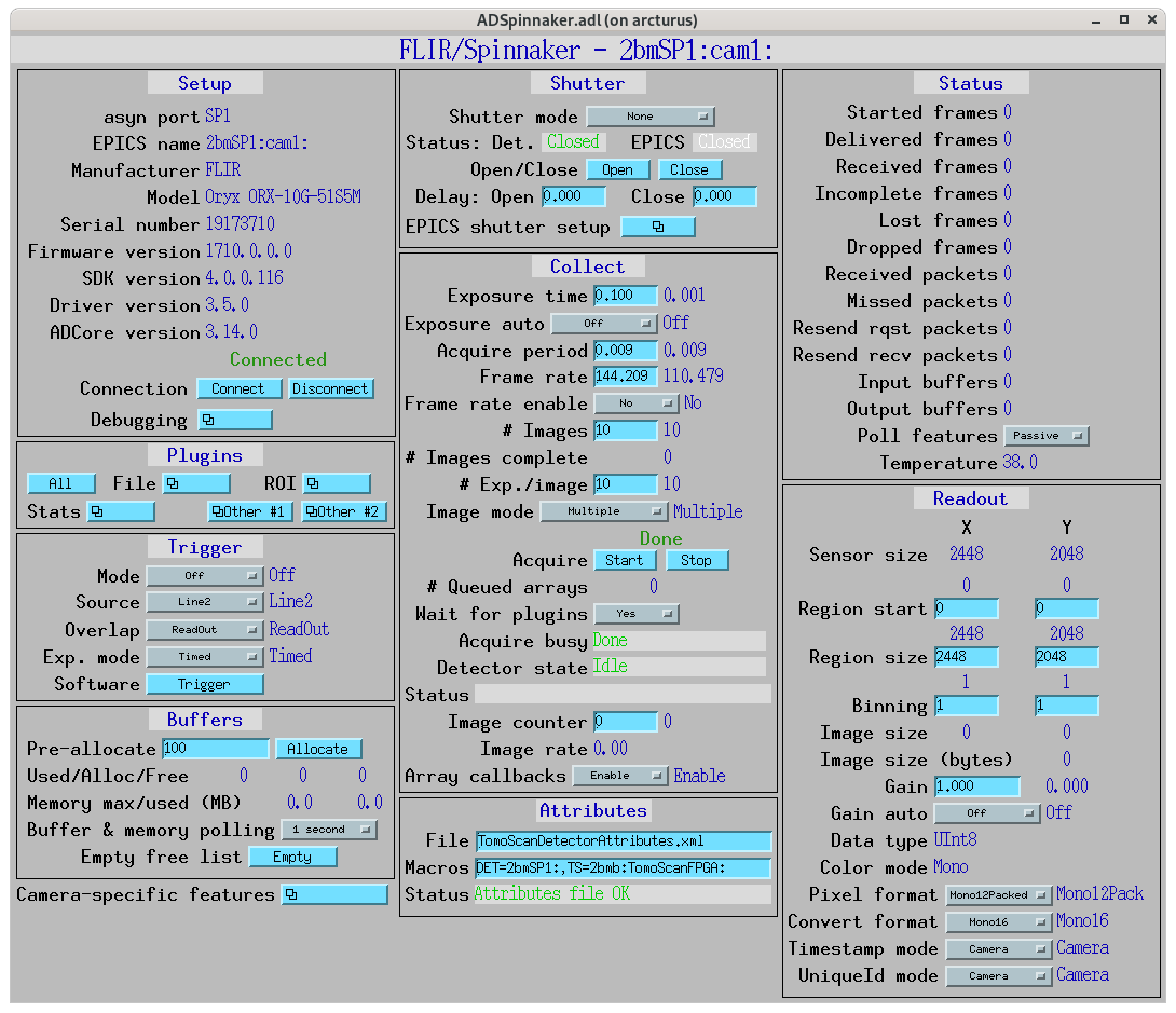
ADSpinnaker.adl for camera 0 (2bmSP1:cam1:, FLIR Oryx
5MP). The Setup panel (top-left) is the source of the per-unit
identification values in the table above.
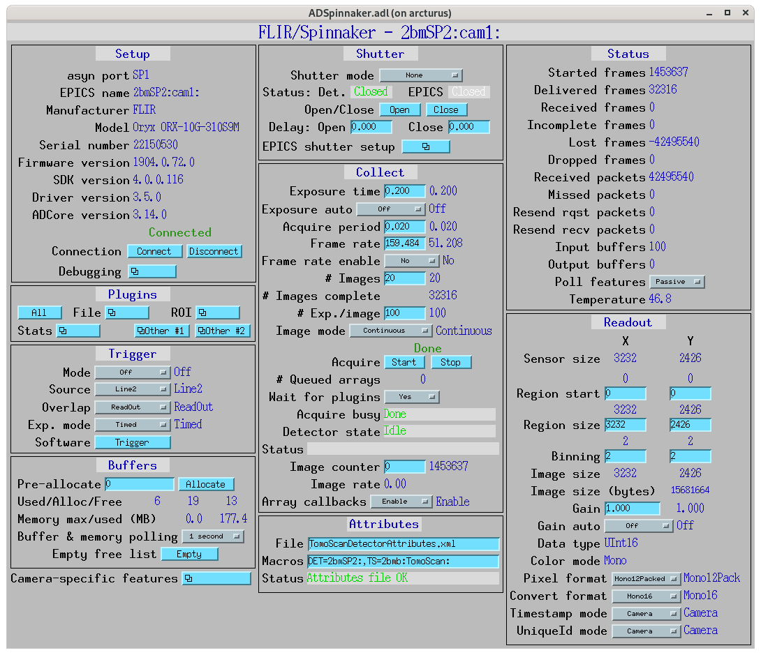
ADSpinnaker.adl for camera 1 (2bmSP2:cam1:, FLIR Oryx
31MP). Same screen layout as camera 0; the Readout panel shows
sensor size 3232 × 2426 because the screen was captured with
2 × 2 binning enabled (native 6464 × 4852).
MCTOptics — Optique Peter IOC
- Role:
EPICS interface that exposes the Optique Peter microscope (objective + camera selectors, per-head focus, per-camera rotation, sample-side alignment) as a single high-level API. Implements the sequencing required so that selecting a lens or camera moves the underlying motors to the calibrated positions and applies the per-combination offsets.
- Family:
Microscope-IOC (composite)
- Repository:
https://github.com/xray-imaging/mctoptics (local checkout:
/Users/decarlo/conda/mctoptics-decarlof/)- Documentation:
- Prefix:
2bm:MCTOptics:- Top-level operator PVs:
2bm:MCTOptics:LensSelect— mbbo,Pos. 0/Pos. 1/Pos. 2(the three objective slots).2bm:MCTOptics:CameraSelect— mbbo,Pos. 0/Pos. 1(Adimec / Dimax, via the folding-mirror camera selector).2bm:MCTOptics:LensSelected,CameraSelected— status readbacks (also report intermediate “Moving between …” state).2bm:MCTOptics:LensName{0,1,2},CameraName{0,1}— string labels (mirror into theLensSelect/CameraSelectchoice strings on init).2bm:MCTOptics:ScintillatorType,ScintillatorThickness,CameraObjective,CameraTubeLength,ImagePixelSize,DetectorPixelSize— optics metadata stamped into each scan.2bm:MCTOptics:CameraBinning(1x/2x/4x) andCamera{0,1}Bit(8/10/12/16-bit).2bm:MCTOptics:Cut{Left,Right,Top,Bottom}+Cut(busy) for image cropping.
Underlying motor map (from iocBoot/iocMCTOptics/mctOptics.substitutions):
Macro |
PV |
Purpose |
|---|---|---|
|
|
Objective selector (turret) |
|
|
Camera selector (folding mirror) |
|
|
Objective #0 focus |
|
|
Objective #1 focus |
|
|
Objective #2 focus |
|
|
Camera 0 rotation |
|
|
Camera 1 rotation |
|
|
Sample alignment in X |
|
|
Sample alignment in Y (hexapod) |
|
|
Sample alignment in Z |
|
|
Camera-0 areaDetector prefix |
|
|
Camera-1 areaDetector prefix |
|
|
Linked TomoScan IOC |
All eight 2bmb:m1–m8 motors in this map plus m17
and m18 are slots on the same OMS-VME58 card — cora Asset
SampleStageDrive. The hexapod motor 2bmHXP:m3 is one
DoF of Hexapod, driven by HexapodDrive.
Calibrated lens positions are per-camera, not shared. MCTOptics
stores six turret positions (3 lenses × 2 cameras) so that the
rotation axis stays at the same physical location when the operator
swaps cameras. When LensSelect or CameraSelect changes, the
IOC moves 2bmb:m1 to the position corresponding to the new
(lens, camera) pair. PVs and operator-verified values
(caget 2026-06-19):
Lens / mag |
Camera 0 (mm) |
Camera 1 (mm) |
|---|---|---|
Lens 0 / 1.1× |
|
|
Lens 1 / 2× |
|
|
Lens 2 / 10× |
|
|
The per-camera offsets are ~0.4–0.6 mm and reflect the slightly
different optical-path alignment between the two cameras on the
dual-port (the folding-mirror selector at 2bmb:m5 swings the
beam between the two camera arms). Operators rarely retune this
alignment in routine operation; the per-camera position table is
the mechanism that lets the IOC preserve the rotation-axis
location across camera swaps when the alignment is fresh.
Camera-selector positions (folding-mirror motor 2bmb:m5):
Pos. 0 = 20 mm, Pos. 1 = 15 mm.
Per-(camera, lens) camera rotation offsets follow the same
lookup pattern as the turret positions above, on a different pair
of motors: 2bmb:m7 (CAM0_ROT, camera 0 image-rotation
alignment) and 2bmb:m8 (CAM1_ROT, camera 1). Same
rationale: keep the rotation axis aligned to the image as the
operator swaps lens or camera. Operator-verified values
(caget 2026-06-19):
Lens / mag |
Camera 0 rotation ( |
Camera 1 rotation ( |
|---|---|---|
Lens 0 / 1.1× |
|
|
Lens 1 / 2× |
|
|
Lens 2 / 10× |
|
|
When the operator changes LensSelect or CameraSelect, the
IOC reads the matching Camera{N}Lens{M}Rotation PV and writes
its value to 2bmb:m7 (if camera 0) or 2bmb:m8 (if camera 1).
This is parallel to the turret-position lookup: same per-(camera,
lens) pair, different motor.
Unit follows the motor record’s .EGU field for 2bmb:m7 /
2bmb:m8 (typically degrees for a camera rotation stage; verify
with caget 2bmb:m7.EGU).
Per-(camera, lens) fine focus offsets are the third 6-PV
lookup family, this time on per-LENS focus motors:
LENS0_FOCUS / LENS1_FOCUS / LENS2_FOCUS =
2bmb:m2 / 2bmb:m3 / 2bmb:m4. Structurally different
from turret position (single motor m1) and camera rotation
(per-camera motor m7 or m8): focus has a different motor
per lens, and the per-camera dimension is currently degenerate
(Camera 0 and Camera 1 hold identical focus values for every
lens in the present calibration). Operator-verified values
(caget 2026-06-19):
Lens / mag |
Camera 0 focus |
Camera 1 focus |
|---|---|---|
Lens 0 / 1.1× → |
|
|
Lens 1 / 2× → |
|
|
Lens 2 / 10× → |
|
|
When LensSelect changes to slot M and CameraSelect is
N, the IOC writes Camera{N}Lens{M}Focus to 2bmb:m{2+M}.
The per-camera dimension is supported by the IOC infrastructure
but is not used in the current calibration (Camera0Lens{M}Focus
== Camera1Lens{M}Focus for every M); the PVs exist for
future per-camera focus calibration if needed.
Summary — three per-(camera, lens) MCTOptics lookups, applied coordinately on each LensSelect / CameraSelect change:
Lookup |
Motor(s) |
Value PVs |
Per-camera dimension today |
|---|---|---|---|
Turret position |
|
|
active (~0.4–0.6 mm offset) |
Camera rotation |
|
|
active (some zero, some non-zero) |
Per-lens fine focus |
|
|
degenerate (Cam0 == Cam1) |
18 calibration PVs in total. Whichever subset is non-degenerate in any given calibration, all 18 lookups exist and the IOC will apply each on LensSelect / CameraSelect changes.
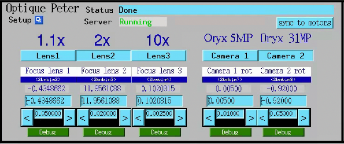
MCTOptics operator screen. Top: server status and the
sync to motors button. Middle: the three lens slots
(Lens 0 = 1.1×, Lens 1 = 2×, Lens 2 = 10×), each with its own
focus value. Right: the two cameras (Camera 0 = Oryx 5MP,
Camera 1 = Oryx 31MP) with their rotation offsets. The
Default button restores the per-combination calibrated
focus / rotation values from the IOC’s autosave file.
PropagationDistance
(cora Asset identifier. Previously called Focus (cora #111)
and “Optique Peter Z stage” (this page); both names were
misleading — this stage controls the sample-to-detector distance
along the beam, NOT lens focus. The propagation distance is what
the operator increases for phase-contrast imaging.)
- Role:
Sample-to-detector Z stage. Carries the entire microscope body along the beam from near-contact with the sample out to ~1 m, varying the propagation distance used to control inline phase contrast.
- Family:
LinearStage
- Model:
Aerotech PRO225SL-1000 mechanical-bearing linear stage (SL precision class, 1000 mm travel; the longest member of the PRO225SL family). cora Model:
aerotech_pro225sl_1000.- Motor:
Aerotech BM250_UF, 240 VAC AC servo motor, S/N
234848-07. This is the motor inside the PRO225SL stage that drives the ball screw (the stage’s product name is PRO225SL-1000; the motor’s vendor part number is the BM250 series). ThePropagationDistanceDriveAerotech controller is the electronics box that runs this motor; see that Asset for the drive’s own model + serial.- Mounted on:
Detector optical table
- Carries:
Optique Peter MICRX080 microscope
- Driven by:
PropagationDistanceDrive(coraMotionControllerAsset wrapping the Aerotech Ensemble HLe 10-40-A-IO-MXH (HLe subseries, 10 A, 40 V bus,-A-option,-IO-option, MXH option; full P/N as printed on the label:EnsembleHLe10-40-A-IO-MXH), S/N228849-02, operator-confirmed against the hardware label 2026-06-16. This resolves the prior “specific product line not yet confirmed” placeholder and the coraaerotech_2bmbaero_drive_unknown_pnModel row. The drive is what the2bmbAEROIOC manages; the Asset wasFocusDrivein cora #111, renamed to match the stage it drives.)- Travel:
1000 mm
- Accuracy:
±18 µm (SL Standard; calibrated grade not offered above 500 mm)
- Resolution:
0.1 µm (high-resolution feedback) / 1.0 µm
- Repeatability:
±1 µm bidirectional
- Straightness:
±9.5 µm horizontal and vertical
- Angular error:
110 µrad pitch, roll, and yaw
- Max speed:
140 mm/s (1000 mm variant; shorter PRO225SL travels reach 220 mm/s)
- Load capacity:
100 kg horizontal, 60 kg vertical (axial), 100 kg side
- Moving mass:
7.3 kg (with tabletop)
- Stage mass:
40.9 kg (without motor)
- Material:
anodised aluminium
- MTBF:
20,000 h
- EPICS:
2bmbAERO:m1(motor record; the table-level VAL field is2bmbAERO:m1.VAL). Lives in a dedicated Aerotech IOC,2bmbAERO, separate from the main2bmbIOC.
Detector optical table
- Role:
Floor-referenced support for the Optique Peter Z stage and the microscope; used to keep the detector centred on the beam as the Z stage moves.
- Family:
Table (cora
TableFamily, declared in the cora catalog atcatalog/catalog.yamland pending registration as AssetDetectorTableindocs/deployments/2-bm/assets.md. The six virtual axes on2bmb:table3are this Asset’saxis_layout = virtual_posesettings value, with the composite record name held invirtual_recordand the SRI 3-Y / 2-X / 1-Z support layout ingeometry— a settings difference from the sampleTableAsset, not a Family split.)- Mounted on:
Hutch floor
- Carries:
Optique Peter Z stage (and the microscope)
- Degrees of freedom:
X, Y, Z, AX (pitch, rotation about lab-X outboard, corrects vertical slope), AY (yaw, rotation about lab-Y vertical, corrects horizontal slope), AZ (roll, rotation about lab-Z beam axis) — six virtual axes computed from six underlying support motors.
- Geometry:
SRI(Sector Research Instrumentation: 3 Y supports, 2 X supports, 1 Z support — 6 motors total).- EPICS:
Virtual table record
2bmb:table3(composite). Loaded in the 2-BM-B IOC bydbLoadRecords("$(DIR)/table.db", "P=2bmb:,Q=Table3,T=table3, M0X=m13,M0Y=m14,M1Y=m12,M2X=m10,M2Y=m9,M2Z=m11,GEOM=SRI").
Underlying motor map:
Macro |
Motor PV |
Role on the table |
|---|---|---|
|
|
corner 0 — X support |
|
|
corner 0 — Y support |
|
|
corner 1 — Y support (no X here) |
|
|
corner 2 — X support |
|
|
corner 2 — Y support |
|
|
corner 2 — Z support (single Z) |
The table.db template combines these into composite translate /
rotate axes 2bmb:table3.X, .Y, .Z, .AX, .AY,
.AZ, plus per-leg readbacks under the 2bmb:table3: prefix.
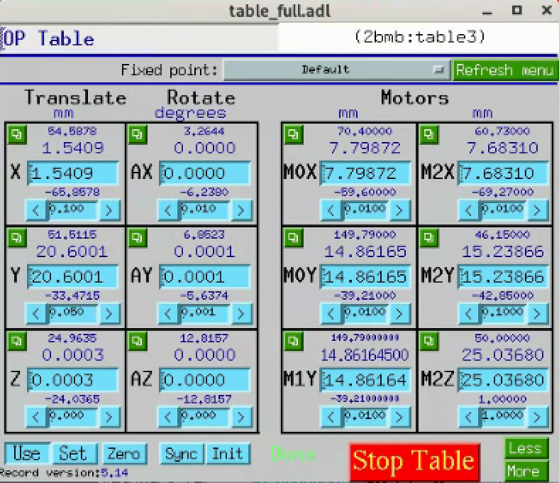
table_full.adl MEDM screen for 2bmb:table3 (the detector
optical table under the Optique Peter instrument). The Translate
and Rotate columns are calc-driven composites; the Motors column
shows the six underlying motor records listed above.
Note
Procedure that commands this table.
Detector Z-rail alignment to the beam (detector_z_rail_alignment)
uses 2bmb:table3.AX (pitch) and .AY (yaw) to rotate the
Optique Peter Z rail back parallel to the beam after a small
square X-ray spot is observed to drift across the camera as the
Z stage translates. This is the procedure that justifies
registering a DetectorTable Asset (cora Table Family)
on the cora side.
Trigger and synchronisation
The Aerotech Ensemble rotary controller emits a position-synchronised output (PSO) pulse every fixed number of encoder counts of the sample rotation. Those pulses are not wired straight to the detector — they pass through a softGlueZynq FPGA that conditions them (pulse width and delay), can mask them through a programmable lookup pattern, and only then drives the camera trigger input.
softGlueZynq (PSO → camera trigger)
- Role:
Conditions and gates the Aerotech rotary PSO pulse train into the detector trigger input. Provides programmable pulse width and delay, a 2:1 MUX between raw PSO and a software-defined custom pattern (
trigILF), and amemPulseSeqblock for arbitrary interlaced sequences.- Family:
TimingController(cora’s Pending entrysoftGlueZynq_FPGAcarries FamilyTimingController— the second<Domain>ControllerFamily afterMotionController. Affordance isPulsingvia theControllerRole: the timing box is itself the actor, not a driven device. Substrate “FPGA” is not a Family axis; theTriggerFPGAplaceholder we previously cited has been superseded byTimingControllerper cora’s #89.)- Hardware:
APS softGlueZynq — Xilinx Zynq SoC (FPGA + ARM) on a MicroZed-class carrier. The EPICS IOC runs on the ARM core and starts automatically at boot.
- Mounted on:
Hutch electronics rack
- Inputs:
PSO output of the Aerotech Ensemble drive that runs the rotary
2bmb:m102.- Outputs:
Camera trigger input. Per
tomoscan/tomoscan_fpga_2bm.py, the wiring is FLIR OryxLine2for the current Oryx 5MP / 31MP cameras; the same module also supports Grasshopper3 (Line0) and Adimec (continuous-timed) modes if those cameras are swapped in.- Signal path:
PSO →
MUX2-1(selects raw PSO ortrigILF) →GateDly 1(pulse width / delay; default 100 × 100 ns = 10 µs) → camera trigger.- EPICS prefix:
2bmbMZ1:SG:. Key PVs:PV
Purpose
2bmbMZ1:SG:MUX2-1_SEL_SignalSelects raw PSO (0) or
trigILF(1) onto the trigger.2bmbMZ1:SG:memPulseSeq.enableArms (1) / disarms (0) the custom-pattern playback.
2bmbMZ1:SG:GateDly1.DLYDelay from input edge to start of output pulse.
2bmbMZ1:SG:GateDly1.WidthOutput pulse width, in 10 MHz clock cycles (100 = 10 µs).
- IOC location:
/net/s2dserv/xorApps/epics/synApps_SG/ioc/2bmbMZ1/onarcturus. Start with./start_epics_2bmbMZ1(or the matching./start_caQtDM_2bmbMZ1for the operator screens).- tomoscan integration:
TomoScan2BM(subclass ofTomoScanFPGAPSO) in tomoscan/tomoscan_fpga_2bm.py selects the camera-specific trigger mode (set_trigger_mode_oryx/_grasshopper/_adimec); the baseTomoScanFPGAPSOclass drives the PSO configuration on the Aerotech controller.- Custom pulse patterns:
For interlaced-fly tomography, pulse subsets are loaded with the helper
macros_ILF.write_PSO_array(e.g.write_PSO_array([0, 2, 4, 6])triggers only on PSO edges 0, 2, 4, 6). See interlaced/fpga/macros_ILF.py.- Notes:
Softglue is the operational page for the FPGA — MEDM screens, how to set
DLYandWidth, how to flip the MUX, and thememPulseSeqworkflow.
Composite IOCs
Some kinematic relations and motion logic are encapsulated inside custom EPICS IOCs and exposed to the rest of the beamline as higher-level PVs. Where this is the case, the underlying stack does not need to be modelled separately in cora: the IOC presents the composite as a single addressable surface.
Each entry below declares:
- Encapsulates:
underlying motors / devices the IOC drives
- Exposes:
higher-level PVs presented to EPICS
- Repository:
link to source
Convention: components whose kinematic role is fully captured by a
composite IOC do not need a Mounted on / Carries chain in the
sections above; they appear only inside the IOC’s Encapsulates
list.
Energy-change IOC
- Encapsulates:
All motors moved together during an energy change. The IOC stores per-energy positions in a configuration file and drives them as a coordinated move. Categories from the current configuration:
Mirror (M1): angle (
m1angl) and average Y (m1avg, derived from2bma:m2and2bma:m5) — both are deflection- geometry parameters held constant in the current configuration (m1angl= 2.615 mrad,m1avg= 0) and would only change if the overall beam-deflection geometry were retuned. The per-energy mirror action is horizontal stripe selection viam1_horizontal(=2bma:m3) and the optical-table X stagesm1moxandm1m2x(from thetable_fullIOC). The stripe sets the high-energy cutoff (low-pass filter via the coating’s reflectivity edge).DMM: all nine motors from the table above except
M2 Z(2bma:m8) — that one is not driven by the IOC. Driven set:dmm_usx,dmm_dsx,dmm_usy_ob,dmm_usy_ib,dmm_dsy,dmm_us_arm,dmm_ds_arm,dmm_m2_y.Downstream / B-hutch:
table3y,flag,b_slit_top,b_slit_bot— these track the downstream beam position. In Mono mode the DMM Bragg geometry shifts the beam exit vertically per energy, so the downstream table, flag, and B-hutch slits move with it to keep the beam in the pipe and centred on the slits. In Pink mode the DMM is bypassed and no per-energy tracking is needed.Filter:
fltr1select(downstream filter paddle index).
- Modes:
Two operating modes are stored:
Mono — multilayer monochromator engaged. DMM Y motors held at 0 (in beam); Bragg arms (
dmm_us_arm/dmm_ds_arm) anddmm_m2_yvary per energy to set the Bragg condition and compensate the beam-exit offset. Mirror stripe held at the lowest position (m1_horizontal= 1.0, table X = 8.0). Downstream (table3y/flag/ B-hutch slits) tracks the beam-exit shift per energy. Currently configured: 13.374, 13.574, 18.0, 20.0, 25.0, 25.584 keV.Pink — DMM bypassed (all DMM Y motors at −10, out of beam); Bragg arms parked at fixed retracted positions. With the DMM out the beam goes straight through, so the downstream motors are held at neutral positions (
table3y= 0,flag= 0, slits wide open). The mirror’s stripe selector handles the high-energy cutoff: low energies use the soft Pt / low-d stripes, higher energies sweepm1_horizontalplus the table X to reach the harder multilayer stripes. Currently configured: 30, 40, 50, 60 keV.
- Exposes:
Higher-level energy-change command surface (PV / RPC TBD; consult
energyApp/in the repository).- Repository:
https://github.com/decarlof/energy.git (standard EPICS app layout —
energyApp/,iocBoot/,configure/,src/).
Mirror stripe travel (Pink mode). m1_horizontal (the in-vacuum
2bma:m3) reaches the low-energy stripes alone; for higher energies
the table X is extended together with it:
Energy [keV] |
|
|
|---|---|---|
30 |
3.039 |
8.0 / 8.0 |
40 |
13.0 |
10.0 / 10.0 |
50 |
39.0 |
10.0 / 10.0 |
60 |
49.0 |
29.0 / 29.0 |
Stored configurations. Per-energy positions are persisted with
ISO-8601 timestamps in a store_0 field, so the most recent saved
values for each energy are what the IOC loads on the next move. The
configuration file is the authoritative source for which motors the
IOC drives — adding a new motor to the energy move means adding its
key to that file, not editing the IOC source.
Why this matters for cora. The energy-change IOC is the canonical example of a kinematic / orchestration relation that is not present in the asset tree but is real and load-bearing for operation. A single “set energy to 50 keV” command resolves into ~15 coordinated motor moves spanning the mirror, the DMM, the downstream table, the B-hutch slits, and the filter changer. From cora’s perspective the energy change should be one Method on a composite “BeamEnergy” surface; the underlying motor stack stays hidden inside this IOC.
MCTOptics IOC
- Encapsulates:
All motors and combination logic of the Optique Peter triple-objective microscope. From the underlying motor map (
iocBoot/iocMCTOptics/mctOptics.substitutions): lens turret (LENS_MOTOR = 2bmb:m1), camera selector (CAMERA_MOTOR = 2bmb:m5), per-objective focus (LENS{0,1,2}_FOCUS = 2bmb:m{2,3,4}), per-camera rotation (CAM{0,1}_ROT = 2bmb:m{7,8}), and sample-side alignment (LENS_SAMPLE_X = 2bmb:m18,LENS_SAMPLE_Y = 2bmHXP:m3,LENS_SAMPLE_Z = 2bmb:m17). When the operator changes the lens or camera selection, the IOC drives the corresponding motor to the calibrated position and applies the per-combination focus and rotation offsets from its autosave file.- Exposes:
Higher-level operator surface under prefix
2bm:MCTOptics:. Setpoints:LensSelect,CameraSelect(mbbo,Pos. 0/Pos. 1/Pos. 2). Status readbacks:LensSelected,CameraSelected(also report the intermediate “Moving between …” state). Labels and stamped scan metadata:LensName{0,1,2},CameraName{0,1},ScintillatorType,ScintillatorThickness,CameraObjective,CameraTubeLength,ImagePixelSize,DetectorPixelSize,CameraBinning,Camera{0,1}Bit,Cut{Left,Right,Top,Bottom}. The full per-PV semantics live in the MCTOptics block above (the operator-facing block); this entry is the composite-IOC contract that downstream consumers (cora included) bind against.- Repository:
https://github.com/xray-imaging/mctoptics (documentation: https://mctoptics.readthedocs.io).
Why this matters for cora. Lens and camera selection at 2-BM
are not raw motor moves — they are composite operations that depend
on per-combination calibration values held in the IOC’s autosave.
Treating 2bmb:m{2,3,4} or 2bmb:m1 as bare motors and
addressing them directly from cora would bypass that calibration
and re-implement (badly) what MCTOptics already does. The cora
binding for the microscope should target the 2bm:MCTOptics:*
PVs above; the underlying motor stack stays hidden inside this IOC.